
If you're interested in building your own DIY DC buck power supply, this guide will walk you through assembling a mini 24V high-voltage DC buck converter.
This isn't a full-on DIY from scratch — it's more about assembling and housing the components properly in an enclosure.
To start, you'll need a high-voltage DC buck module that can take an input of up to 80V and output 24V at 1.2A. The module looks like the one shown below.
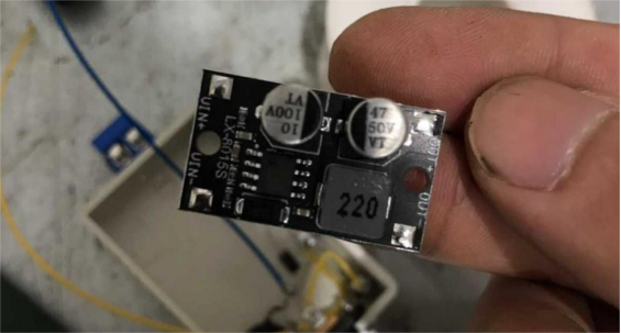
Based on the 8015 chip used in the module, its maximum rating is likely around 80V at 1.5A. However, real-world testing shows that when stepping down from 60V to 24V at 1A, the module heats up significantly — easily hitting 50°C. That's not ideal. Fortunately, for use as a control power source, you don't need that much current. A steady 0.5A is more than enough.
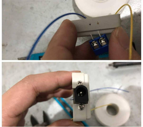
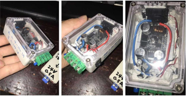
You'll also need an ABS plastic enclosure. Mount a DC input jack on one end and output terminals on the other. Since this module doesn't come with reverse-polarity protection on the input, it's a good idea to add a reverse-biased diode and a 0.5A fuse in series.
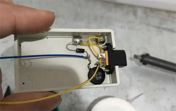
In case you connect the input the wrong way, the fuse will blow to protect the circuit. You should also account for the large spark that occurs when connecting high-voltage DC — it can be strong enough to damage the DC plug. To reduce this surge, include an NTC thermistor in series.
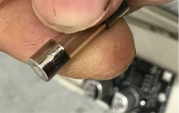
Add another 0.5A fuse on the output side as well, just to limit current in case of overload. For instrumentation and control circuits, power demand is very low, so this is sufficient.
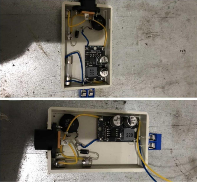
Once everything is wired, you can fit the module neatly into the box and secure it with epoxy for added durability. Despite the compact size, it's important to include all essential protection features.
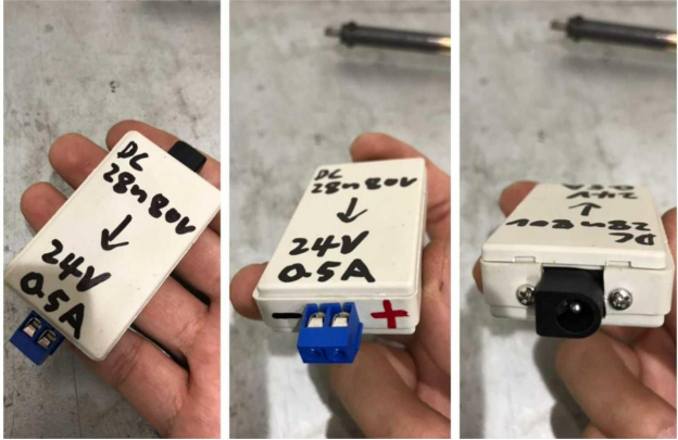
Finally, close the enclosure, label the voltage and current ratings on the outside — and you're done. It should look something like the finished product shown in the image.
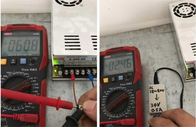
After powering it up, testing shows that 60V DC is already in the dangerous voltage range — it can give you a noticeable jolt. But the output is a stable 24V and the module stays cool.
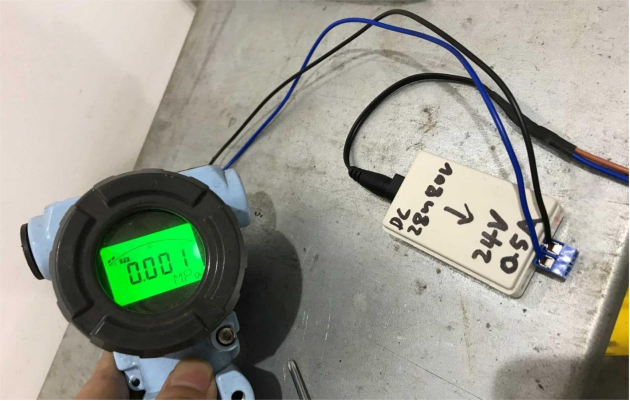
This setup is ideal for powering instruments in high-voltage DC systems, such as in photovoltaic (solar) setups.
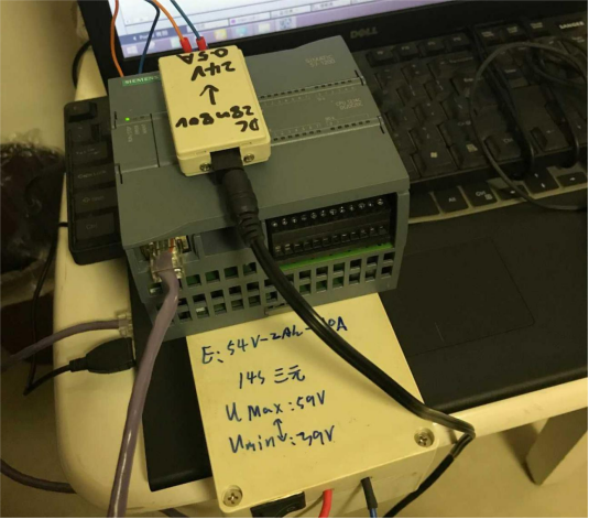
It's also useful for PLC module testing — for example, if you're experimenting with using a PLC controller in a solar system, you could integrate it with a stepper motor and a light sensor to create an automatic solar tracking system. Just keep in mind that the cost adds up, so unless you're planning to take the project further, it might remain a prototype-level experiment.
Note: This small module is designed for instrumentation and control. If you need a more powerful 24V power supply (e.g., stepping down from 110V to 24V at 5A), that's doable — but you'll need to add proper heatsinking and a cooling fan. This higher-power version would be suitable for driving solenoids, electric valves, and similar equipment.


