
If you're curious about the internal structure of the ZOYI ZT-C1 portable auto-ranging multimeter, this article offers a closer look inside.
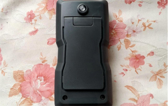
Here's what it looks like from the outside:
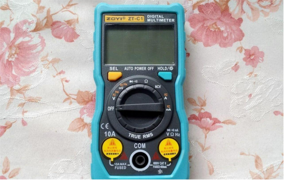
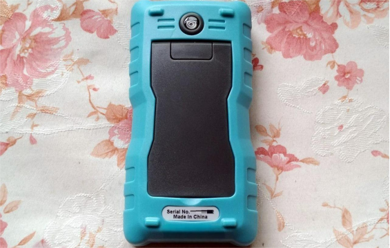
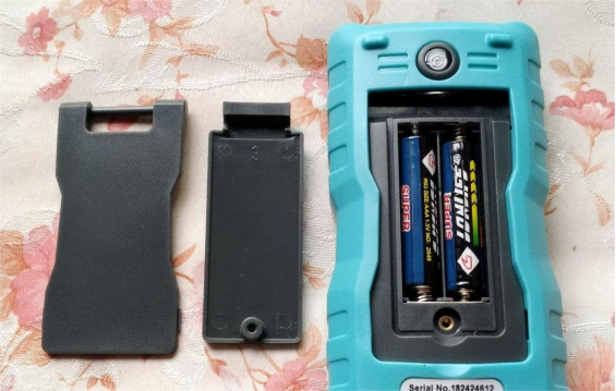
The stand is held in place by the battery cover, and the device runs on two AAA batteries.
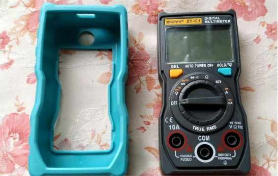
To disassemble it, you'll first need to remove the outer soft PVC protective case.
Back View
The battery compartment on the ZT-C series is located on the back shell.
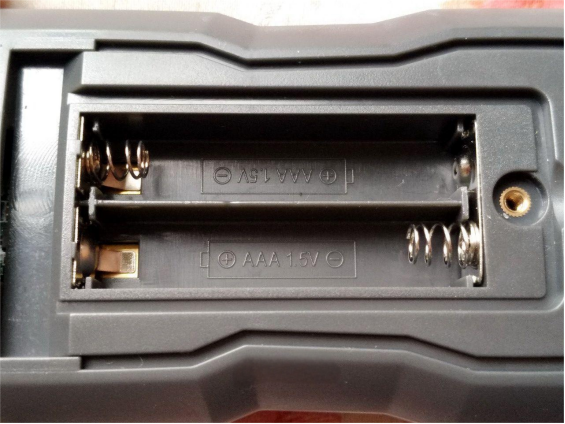
Once that's off, you can open the casing. You'll notice the display probes seem to float, and the last digit may flicker slightly — likely due to a lack of shielding on the rear cover.
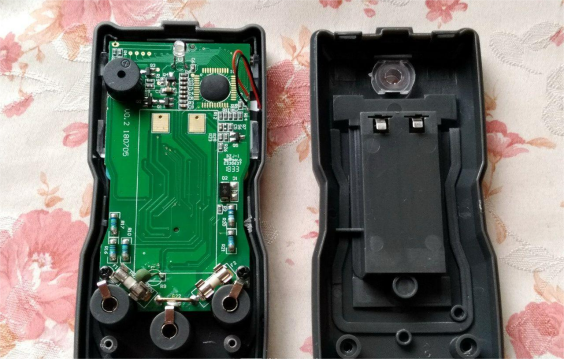
Here's the full view of the circuit board:
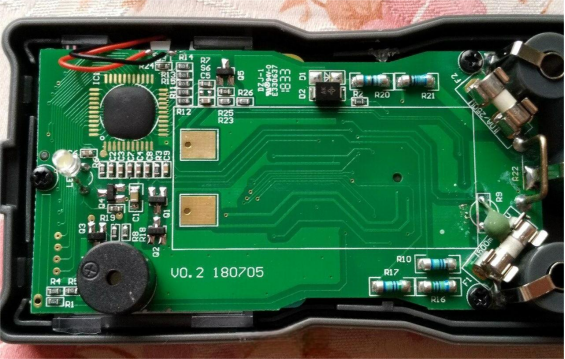
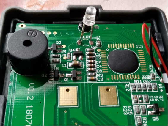
Upper section of the mainboard: Includes a buzzer, battery contacts, and an LED flashlight. On the top-left is the NCV (non-contact voltage detection) sensor wire, likely connected to an SD7830A chip from Hangzhou SDIC Microelectronics.
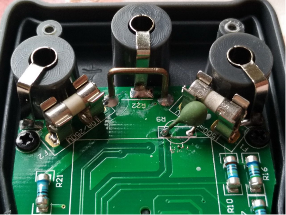
Lower section of the mainboard: Houses the input terminals, current-sensing manganin wire, and a fuse that's smaller than standard ones.
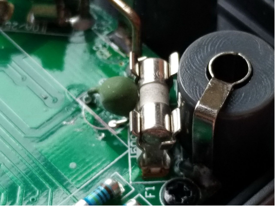
There's also a component that might be an NTC thermistor, possibly used to monitor the fuse temperature.
Here's the board once removed:
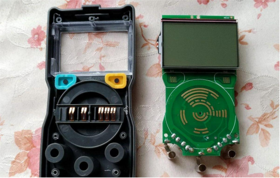
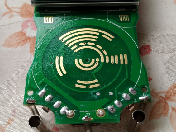
You can see the rotary switch contacts, which have been lubricated.
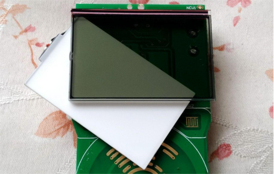
The backlight is connected via a flexible cable, and there are no components under the LCD screen.
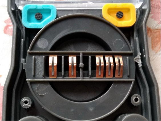
The rotary switch on the front shell is worth noting — you could document the contact positions for reassembly.
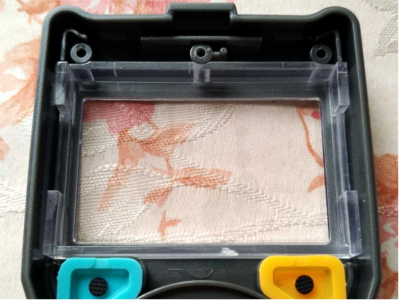
There's also a protective cover over the screen.
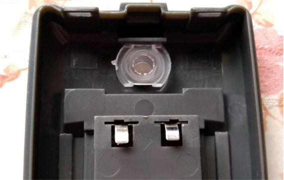
The back shell simply holds the battery contact springs and flashlight lens.
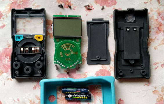
Here are all the disassembled parts laid out:
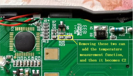
If you're into DIY modifications, here's a tip: try removing the resistor highlighted in the yellow box below. Doing so may effectively convert the ZT-C1 into a ZT-C2. After this tweak, the function dial behaves like that of the C2 — combining the resistance and diode modes, while the original resistance mode becomes a temperature measurement mode.
Done.


