
If you're interested in DIY-ing an IP6538 fast charging module, this article is for you.
In the industry, many fast charging modules use the SW3518 chip, but modules based on the IP6538 are rare or almost nonexistent. So today, let’s explore how to build a module using the IP6538.
Introduction to the IP6538 Chip
Overview:
The IP6538 is an integrated synchronous buck converter SOC chip that supports 14 fast charging protocols. It features dual output ports with support for Type-C output and USB PD 2.0/PD 3.0 (PPS) protocols. It provides a complete solution for automotive chargers, fast chargers, and smart power strips.
The IP6538 supports dual USB Type-C outputs, a combination of USB Type-C and USB-A, or dual USB-A outputs. It integrates automatic plug/unplug detection for both ports. Each port can independently support fast charging, and when both ports are used simultaneously, each outputs 5V with a total power of 5V/4.8A.
The chip includes built-in power MOSFETs, operates with an input voltage range from 8.2V to 32V, and outputs from 3V to 20V. It can deliver up to 45W of power, automatically adjusting voltage and current based on the detected fast charging protocol. At 5V/3A output, the board achieves up to 96.5% efficiency.
The IP6538's output supports CV/CC modes: when the output current is below the set threshold, it operates in constant voltage (CV) mode; if the current exceeds the threshold, it switches to constant current (CC) mode, lowering the output voltage accordingly.
It also features line compensation, meaning the output voltage will rise slightly as output current increases to offset voltage drops caused by cable resistance.
Additional features include soft-start to prevent input power instability during startup, and multiple protections such as input over-voltage, under-voltage, output over-current, over-voltage, under-voltage, and short circuit protection.
The chip comes in a compact 5x5mm QFN32 package.
Key Features
· Synchronous buck converter with built-in power MOSFETs
· Input voltage range: 8.2V to 32V
· Output voltage range: 3V to 20V, automatically adjusted per fast charge protocol
· Line compensation: 50mV/A
· CV/CC output characteristic (CV mode when current < set value, CC mode when current > set value)
· Efficiency: 96.5% at VIN=12V, VOUT=5V/3A
· Dual-port fast charging output:
· Dual USB Type-C outputs
· USB Type-C + USB-A output
· Dual USB-A outputs
· Any single port supports fast charging
· Automatic plug/unplug detection on both ports
· Supports Type-C interface and USB PD protocols:
· Output voltages: 5V, 9V, 12V, 15V, 20V
· PD 2.0 / PD 3.0 (PPS) supported
· PPS output range: 3.3V to 11V, 20mV steps
· Supports multiple fast charging protocols (each supporting 2 ports):
· Type-C PD
· BC1.2, Apple, Samsung
· Qualcomm QC2.0 & QC3.0
· MTK PE+ 1.1 & 2.0
· Huawei FCP & SCP
· Samsung AFC
· Spreadtrum SFCP
· OPPO VOOC & Super VOOC
· Multiple protection features for high reliability:
· Input over-voltage/under-voltage, output short circuit, over-current, over-temperature
· DP/DM/CC pin over-voltage protection (rated up to 30V)
· ESD protection at 4kV, DC withstand voltage 40V
This chip is ideal for low-power applications. The official design uses a 4-layer PCB, but for DIY, a 2-layer PCB is more cost-effective—you can design accordingly.
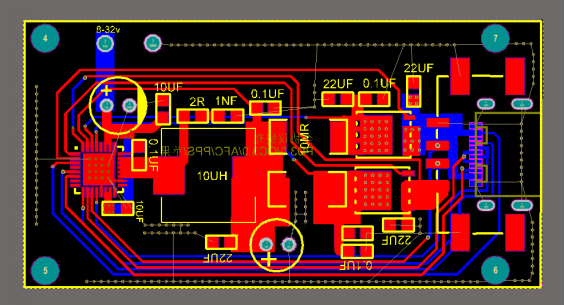
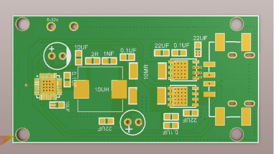
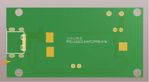
Fast charging module with IP6538 + 5358 power bank module
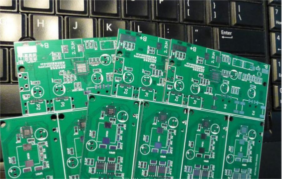
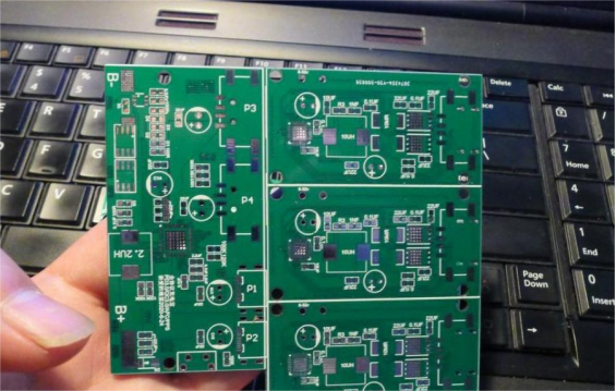
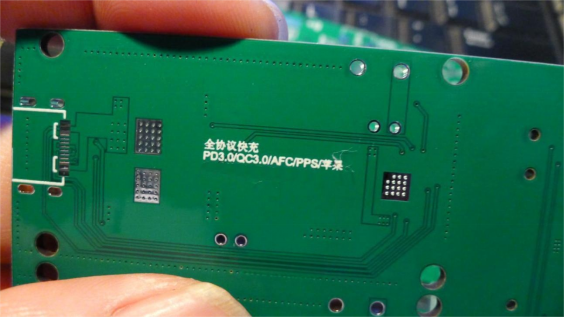
IP6538 chip label
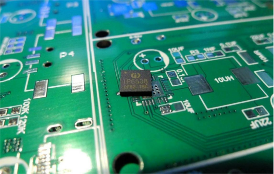
Soldering:
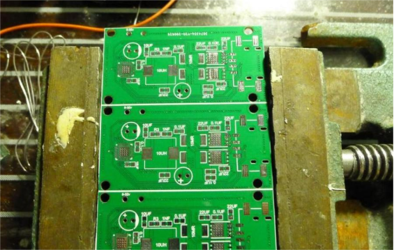
After soldering, you can proceed with testing.
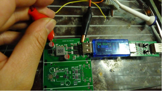
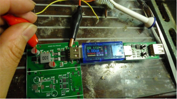
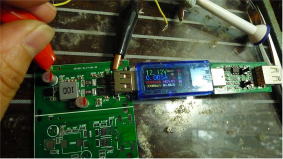
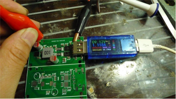
Second Channel Testing:
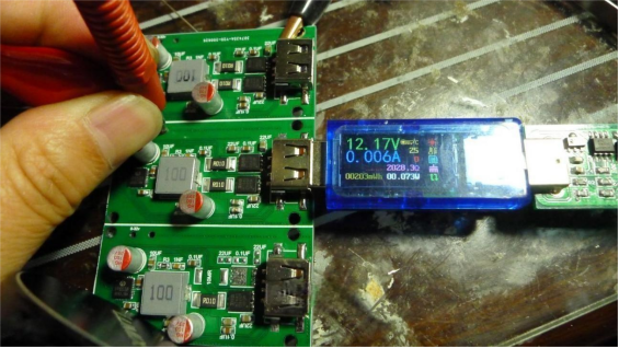
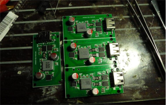
You can make four boards—one for your car and three combined for desktop charging.
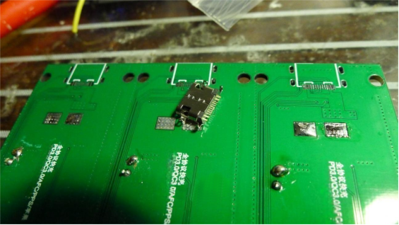
All QC and AFC protocols tested perfectly. Just be sure to get the correct Type-C connector—using the wrong one may prevent PD testing. If that happens, you can wait for new connectors and retest PD later.
End.


