
If you usually collect some circuit boards at home and need to salvage useful components for your DIY projects, but you only have a multimeter on hand, you can use the multimeter to check most components for functionality. However, capacitors are tricky to test with just a multimeter. What should you do?
In that case, you can build an LCF meter along with this article. I found a simple circuit and tried making one.
LCF Meter General Measurement Range
· Inductance Range: 0.1μH to 1H
· Small Capacitance Range: 1pF to 2.2μF (for non-electrolytic capacitors)
· Frequency Range: 50Hz to 400kHz (capable of measuring small signals)
· Electrolytic Capacitance Range: 0.5μF to 12,000μF (both electrolytic and non-electrolytic types)
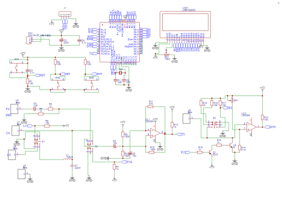
Circuit Schematic
As shown below. You can use an LM393 comparator; if you don't have one, you can salvage an LM339 from old equipment.
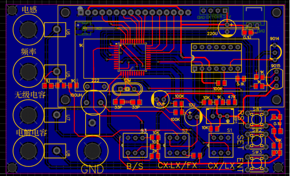
PCB layout shown below
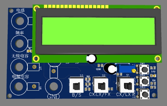
3D preview
This meter cannot be calibrated precisely; its accuracy mainly depends on the precision of a reference capacitor (2200pF) and a reference inductor (100μH).
Completed unit (made with salvaged parts—you can collect parts from various devices during the build process)
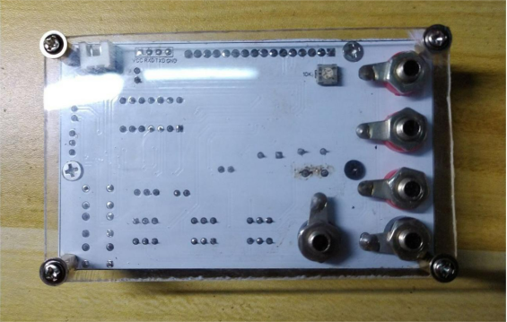
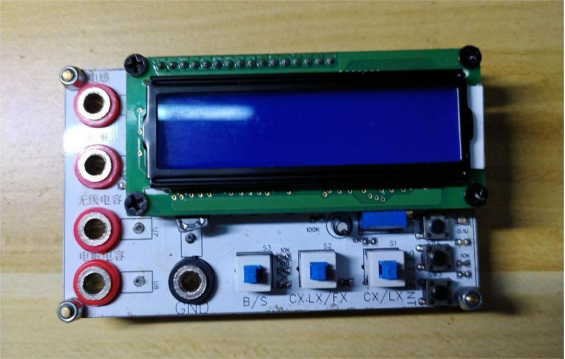
Power it up and test: if the reference components are precise,
(reference: frequency with L=100μH, C=2200pF = 339000Hz)
Measured frequency = 329800Hz, which shows some error.
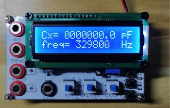
Next, You can further verify the meter by testing various capacitors:
· Measured non-polarized capacitor: 104
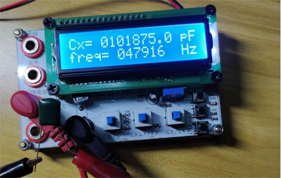
· Measured non-polarized capacitor: 105
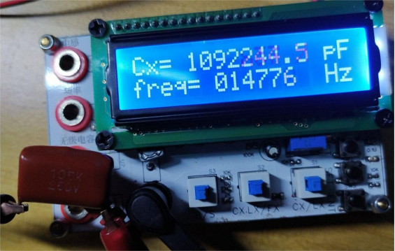
· Measured non-polarized capacitor: 472
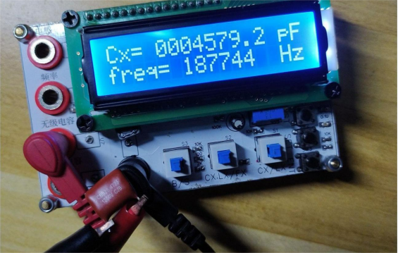
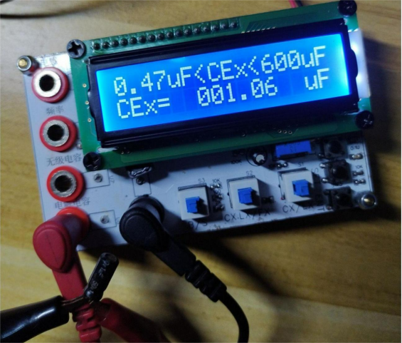
· Measured electrolytic capacitor: 1μF
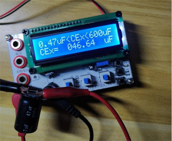
· Measured electrolytic capacitor: 47μF
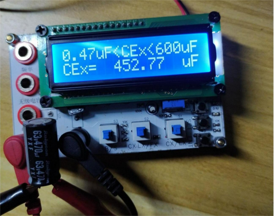
· Measured electrolytic capacitor: 470μF
· Measured electrolytic capacitor: 2200μF
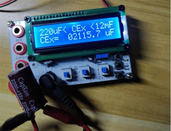
The main purpose of this device is to test whether capacitors are good or bad—the exact precision is not critical. The results exceeded my expectations and work pretty well.
Therefore, other functions were not tested. If you need them, you can DIY and test further yourself.
Done.


