If you're interested in building a DIY TL494 high-frequency inverter, this article might be worth a read.
First, let's understand what the TL494 chip is.
The TL494 is a commonly used Pulse Width Modulation (PWM) controller chip. It's widely used in high-frequency inverter circuits to convert DC power into AC power. Acting as the core control unit of an inverter, the TL494 generates drive signals that control the switching of power transistors, thus enabling the DC to AC conversion.
Building a TL494 High-Frequency Inverter

You can modify a transformer from an electric bike charger for this project.
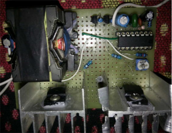
Pin 7 of the TL494 is grounded—this ground line connects to the heatsink, and there's no separate ground wire soldered. One of the TL494's error amplifiers is used for voltage regulation, while the other is left unused (shielded).

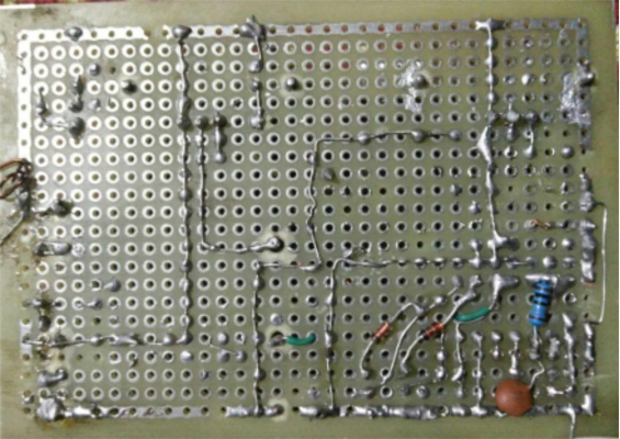
As shown in the image above, solder the back side of the board carefully. You can use clipped component leads as jumper wires for the connections.

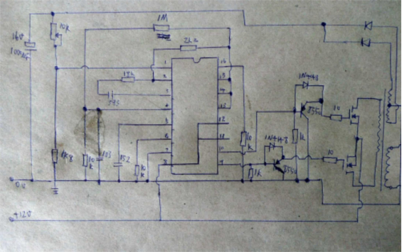
Refer to the circuit diagram shown above.

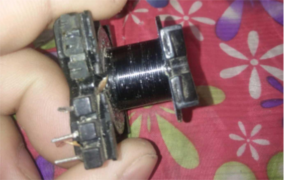
To disassemble the transformer, you can heat it using a hair dryer. This will soften the glue and allow you to pry open the magnetic core. The image above shows the disassembled transformer skeleton.
For winding: twist two primary wires together and wind 20 turns; then wind 400 turns for the secondary; finally, wind 20 turns for feedback.
And that's it — done.
Now try yours!


