
In the last DIY guide DIY Supercapacitor Car Jump Starter Guide, we talked about the materials needed to build a fully automatic supercapacitor starter power supply, as well as the functions and usage of the finished product.
Now, in this part, we'll go through how to actually make this same-port automatic supercapacitor starter power supply.
The most important part is the automatic boost-buck circuit.
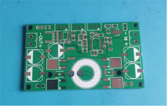
Here's the empty PCB for the automatic boost-buck circuit:
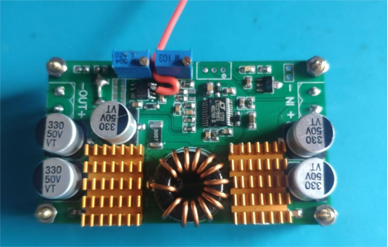
And here's the finished boost-buck board:
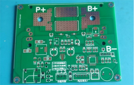
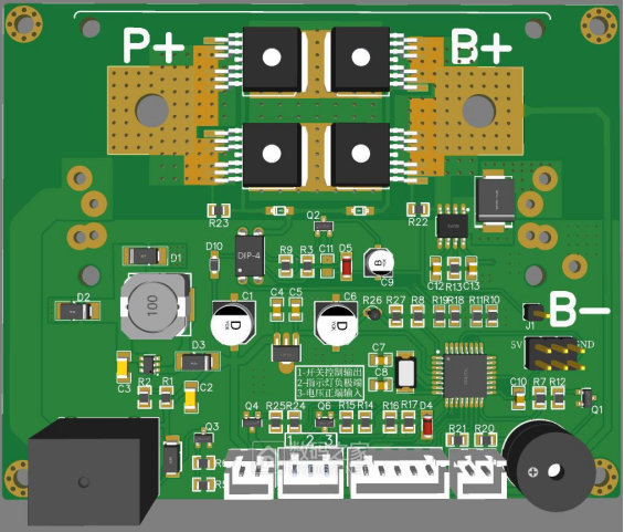
Here's the empty main control board:
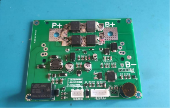
And the finished main control board:
You can also use this improved version:
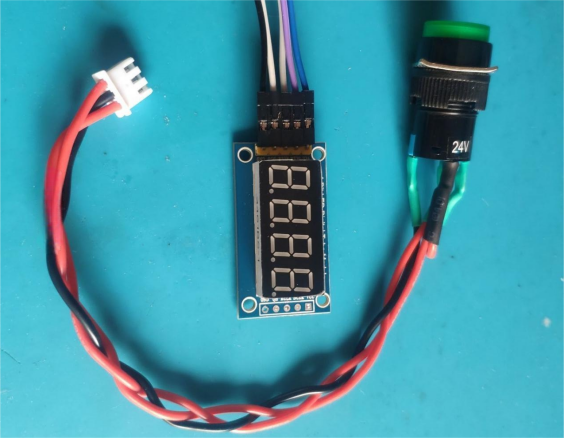
Here's the voltage display module and button switch:
Once you've got all these modules ready, you can start assembly and testing.
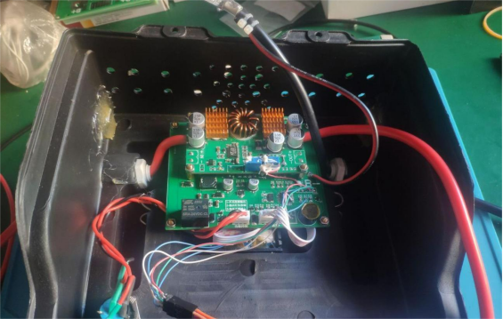
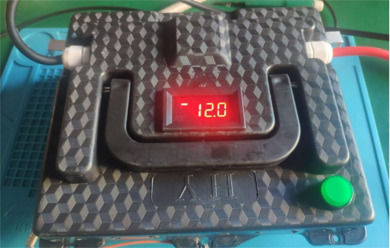
After assembly, it should look something like this:
Supercapacitor Emergency Jump Starter User Guide
Power Overview:
This emergency jump starter uses six Maxwell supercapacitors from the U.S. Inside, it has an automatic boost-buck control circuit and a microcontroller-based program control circuit. It uses a same-port charge/discharge circuit design, which removes the hassle of needing an external charging cable, making it more portable and convenient.
Important Notes:
Never connect the positive and negative clamps in reverse; Never short the clamps together when output is active; Charging requires a DC power source in the range of 5–16V; Below 5V, it won't charge; Above 16V, it will damage the internal control circuit!
(When input power is connected, the unit will start automatically. If input voltage drops below 5V, the jump starter will beep and the indicator light will flash. Press the button once to silence the buzzer and turn off the indicator.)
Power functions and usage instructions:

When the first character shows the upper line lit, it displays the input voltage. When the lower line is lit, it displays the internal voltage. During normal charging, input and internal voltage will alternate. If the external power is disconnected and the voltmeter still shows readings, press the button switch once to turn it off.
1. If the car battery voltage or external charging voltage ≥11V and higher than the jump starter voltage, it will start direct charging mode (when using an external charger, use one with constant current function). The button indicator stays solid.
2. If the car battery voltage or external charging voltage <11V, it will automatically switch to boost charging mode.
3. In boost charging mode, if the jump starter voltage < (minimum start voltage 11V), the button indicator will flash quickly 3 times every 2 seconds.
4. In boost charging mode, if the jump starter voltage ≥ (minimum start voltage 11V), the button indicator stays solid.
5. When jump starter voltage ≥ (minimum start voltage 11V) and the car battery still has some charge, press the switch for more than 3 seconds to enable output. The buzzer will beep at low frequency (enter the car quickly). After 5 seconds, output voltage starts, and the buzzer changes tone. During the next 15 seconds, the vehicle can be started. Output automatically stops after 15 seconds.
· Only when the buzzer changes tone can the vehicle be started. If the car battery is completely dead, keep holding the switch until the buzzer changes tone and the indicator stays solid before releasing to start the car.
6. When jump starter voltage < (minimum start voltage 11V), pressing the switch for more than 3 seconds will make the buzzer sound for 1 second and exit the switch mode.
7. During charging, pressing the switch will toggle charging on or off.
8. Normally, hold the switch to check the current remaining voltage of the power supply.
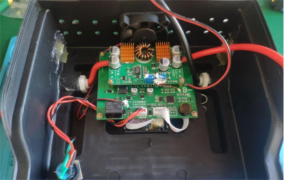
The internal control circuit is shown in the picture above.
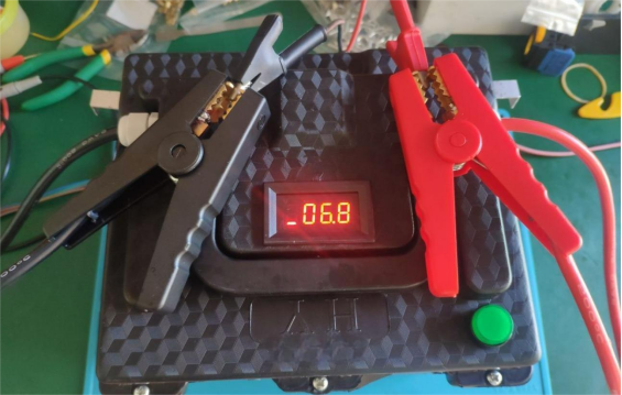
Same-port charging demonstration is shown in the picture above.
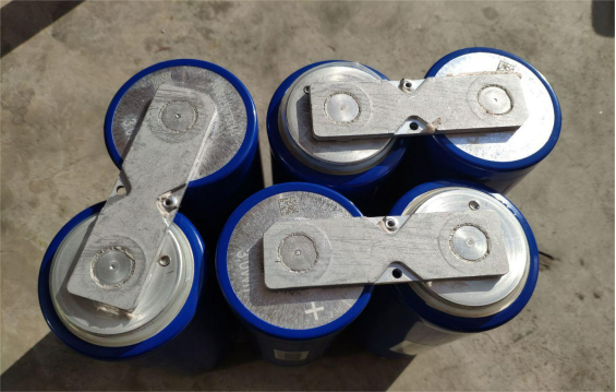
The supercapacitors are shown in the picture above.
Completed.


