
If there If you're interested in DIY-ing a simple hearing aid, you might want to check out this article.
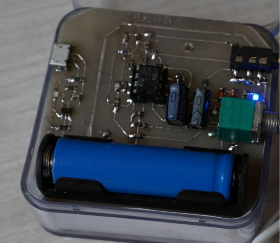
If you also want to make a simple hearing aid yourself, you can try using the TDA2320A—it works really well. After following the steps in this article, the internal structure of the hearing aid will look like the diagram below.
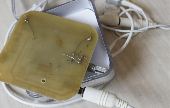
The back of the circuit board looks like this. If it's hard to solder the potentiometer or battery holder on the component side, you can solder a few wires on the back instead.
Commercial hearing aids have limitations on the frequency band, roughly 400 to 4000 Hz, so the circuit needs some modifications. The main points to consider are:
1. Putting the microphone inside the casing might create friction noise (the circuit board still shows where the microphone should be mounted).
2. Connecting the potentiometer in the feedback circuit and compressing high frequencies through feedback can be tricky to implement.
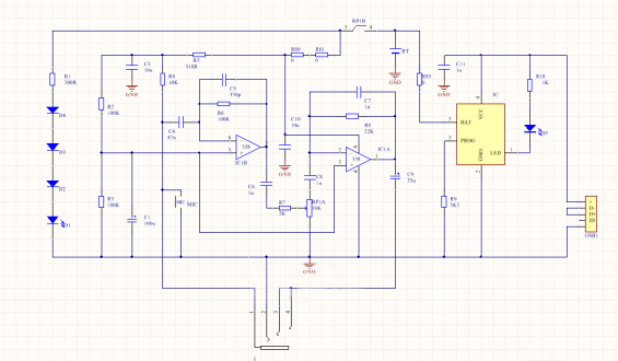
So, the final circuit diagram looks like this. R00–R02 are 0-ohm resistors used as jumpers, and the resistor and capacitor values are for reference only.
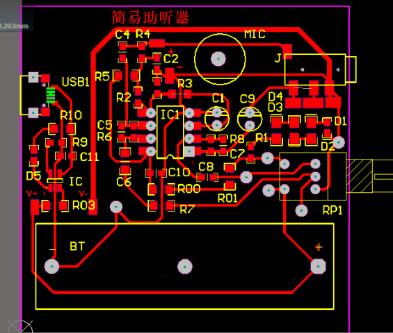
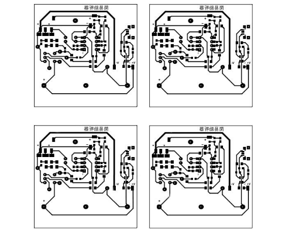
The PCB layout is shown in the diagram below.
The thermal transfer print looks like this.
You can use Sony noise-canceling headphones for this. These headphones have an external microphone that can pick up sound.
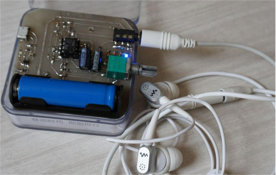
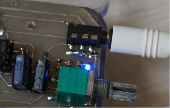
You can connect two headphones in parallel, and the wiring of the headphone jack is brought out so you can change the connection.
If you find that using these noise-canceling headphones doesn't work well—like the microphone is too close to the headphone driver and the hard connection causes feedback—you can try separating the microphone from the headphones. If you have an old cheap hearing aid, you can take it apart, keeping only the microphone and the headphones. Then you'll need an old headphone cable.
If the headphone cable isn't shielded and you're worried that sharing a ground between the headphones and the microphone could cause issues, you can use two separate ground wires. Then, use the other two wires for the headphones and microphone respectively, and adjust the headphone jack wiring at the same time.
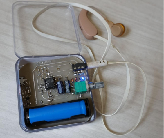
After this modification, the listening experience will improve a lot. It won't feed back easily, and even at high volume, it won't hurt your ears. The headphone jack wiring is changed, and there are now two ground connections.
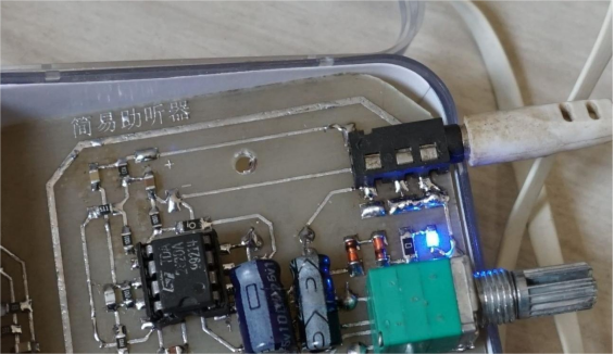
Next, test charging. If everything works, charge it fully; the light will turn off when it's done.
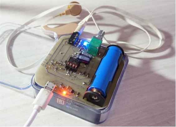
That's it—you're finished. Later, you can replace the headphone cable with a longer, better one if you want. You'll also need to drill holes in the casing to install the components.
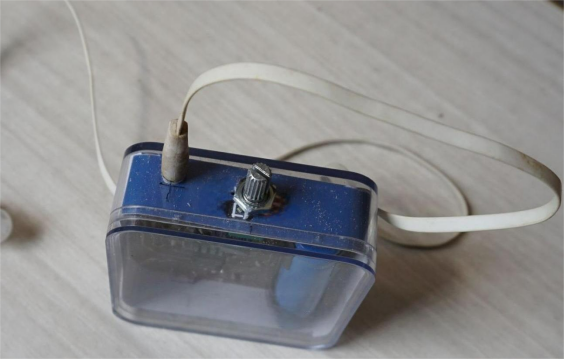
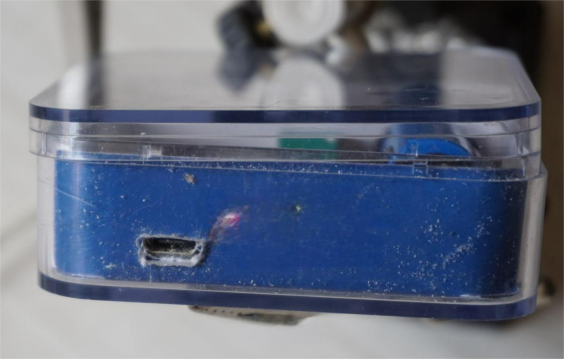
Done.


