
If you're interested in DIY full-bridge inverter audio-modulated plasma speakers, you might want to check out this article.
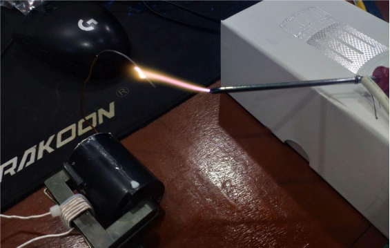
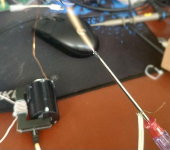
So, what exactly is a plasma speaker? The principle is that high-voltage electricity breaks down the air, creating an electric arc that heats the air. As the air heats up, it expands, and the diameter (thickness) of the arc is proportional to the current flowing through it. The thickness represents how much the air expands. If you make the arc current oscillate within the audio range, it will drive the air to vibrate and produce sound that we can hear.
To achieve this, you need two things: high voltage and modulation. Modulation lets the high-voltage current change according to the audio signal. First, you need to invert DC into AC to drive a high-voltage transformer, and then modulate the current by varying the duty cycle according to the audio signal. Most switching power supply topologies can be used, including flyback, push-pull, half-bridge, full-bridge, or LLC. In this article, we use a relatively complex full-bridge to drive the high-voltage transformer. The 3525 acts as the signal source, driving a full-bridge made from two integrated half-bridge drivers. The advantage is a wide input range and maximum power (topology-dependent). Below is the step-by-step build.
The schematic is shown below:
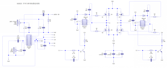
On the left is the signal source schematic. The 3525 is set up in open-loop mode. The error amplifier is configured as a follower, so the voltage on the COMP pin equals the voltage on the non-inverting input. The COMP pin directly controls the output duty cycle, so adjusting the non-inverting input voltage lets you control the output current. After AC-coupling, the audio signal is added to a fixed bias voltage from a potentiometer, which makes the high-voltage transformer "sing." Fixing Ct and adjusting Rt changes the output frequency. The discharge end is connected directly to Ct to minimize dead time.
On the right is the full-bridge power board schematic. The main thing to note is that the RMS current through the full-bridge bus filter capacitor is very high because leakage inductance energy can flow back to the bus. Therefore, you need a capacitor with enough capacitance and low ESR. Non-polarized and/or non-inductive capacitors are preferred, like CBB or MLCC types. Solid-state capacitors are also fine, though their voltage rating isn't very high. Green high-frequency electrolytic capacitors are a common choice, while standard black electrolytics are better than nothing.
Here are photos of the SG3525 signal generator board and the full-bridge power board:
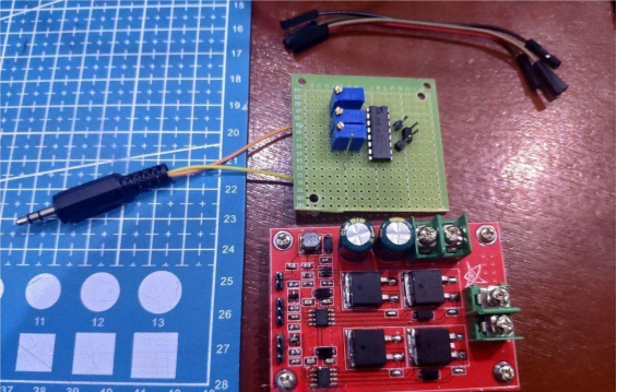
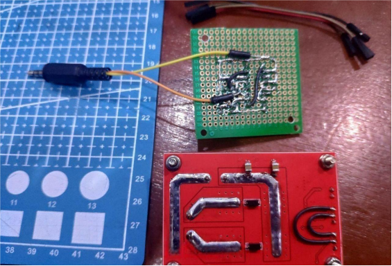
For driving, you can use a fully integrated gate driver like the EG2131 with 1–1.5A output. In tests with a transistor having Ciss of 8nF, the rise time is 200ns and the fall time is 100ns. At 100W load, the bus filter capacitor heats more than the transistors. The biggest advantage is that you don't need to wind a GDT.
You can choose Huayi Microelectronics' switching transistor HY1707, rated 70V, 80A, 6mΩ. Compared to the 3205, aside from lower current, it's better in almost all other specs. You'll also need a small onboard buck converter to provide 12V for the driver and signal board.
This power board can take 32V input, achieve output frequencies up to 100kHz, and with heatsinks and fans, can handle 200–300W.
Here's the bus AC waveform:
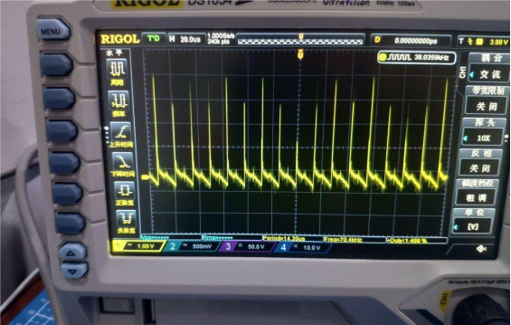
The spikes occur during the switching dead time when leakage energy is recovered through diodes. High-performance snubber capacitors are needed here.
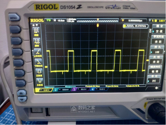
Here's the waveform of the lower transistor gate on one side:
And here's the primary voltage waveform at about 25% duty cycle. This might vary depending on the secondary rectification method of the high-voltage transformer.
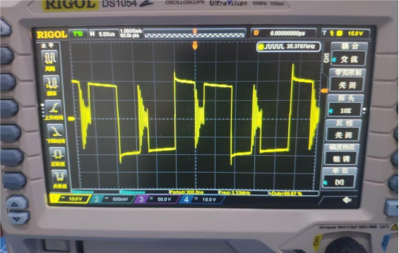
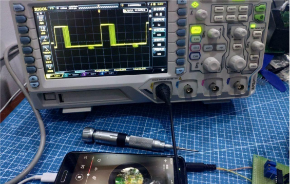
Once you can consistently strike an arc, you can start audio modulation. First, set the duty cycle (or static operating point) to around 20% on one side, then input the audio signal. Adjust the signal amplitude so the duty cycle stays slightly away from the maximum and minimum, preventing clipping. Simply put, ensure that when the music signal peaks, the duty cycle doesn't exceed 45%, and at its lowest, it doesn't go below 5%. In the figure, you can see the duty cycle jumping under the music signal modulation. Using longer persistence on the oscilloscope can help with this adjustment.
Done.


