
If you've been tinkering with digital circuits lately and need a simple way to check voltage levels, then let's DIY a small tool that can do just that. If this sounds interesting, keep reading.
It's not that complicated. The common chip used here is the LM339. You can easily find reference circuits online, and you can see this sample diagram below.

For the resistors, approximate values are fine — they don't have to be exact. Once that's sorted, you can go ahead and make the PCB.
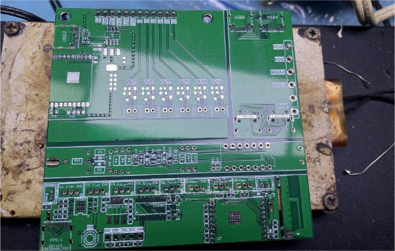
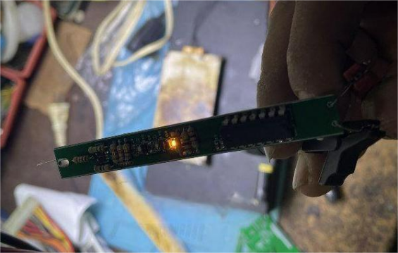
Next, cut out the logic probe section and solder all the components, as shown in the picture.
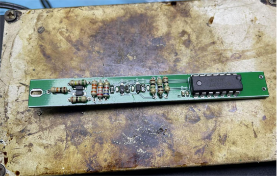
If you have a set of 0805 resistors, you can pair them with an SMD LM339. If not, through-hole resistors will also work. After soldering, you can start testing. As shown below:
· At high level, the red LED lights up.
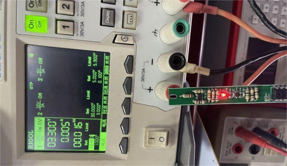
· At low level, the green LED lights up.
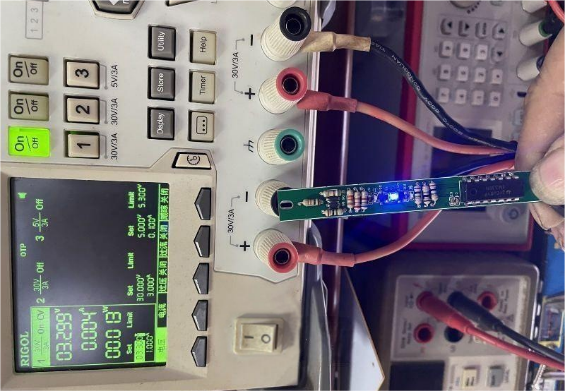
· When floating or high impedance, the orange LED lights up.
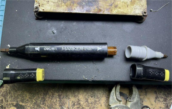
Now you can move on to the casing. Grab an empty marker pen and make three holes in it. The positions don't need to be super precise — just like in the picture.
You'll also need a piece of fishing line. Thread it through the holes first, then glue it to the LEDs with 502 glue. Be sure to thread it before gluing, otherwise it'll be almost impossible to get it through from the inside out.
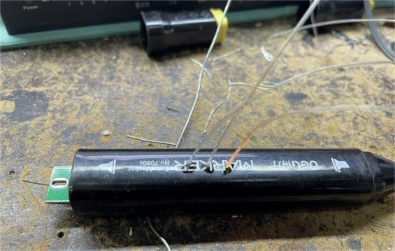
Finally, connect the power wires to the back of the pen, use a short piece of copper wire as the probe at the front, trim the fishing line, and snap the cap back on. Done!


