
If you're interested in a DDS signal generator circuit board, you might want to check out this article.
This DDS signal generator board is basically just a MEGA16 microcontroller with a 358 op-amp. It claims to output square waves up to 8 MHz, while other signals (sine, triangle, sawtooth, reverse sawtooth, square, etc.) go up to 65 kHz. The tricky part is the power supply—you'll need 5 V, 12 V, and –12 V. But if you've got a few 3R33 modules, you can generate negative voltage.
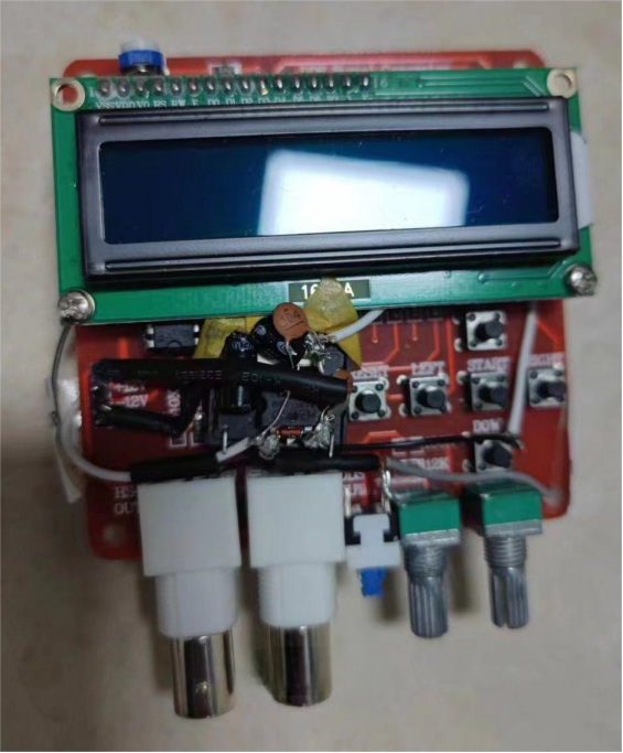
Here's the front view: with 3R33 plus a 7805 regulator, you get ±8 V and +5 V. The +5 V powers the MCU and the display, while the ±8 V powers the 358 op-amp.
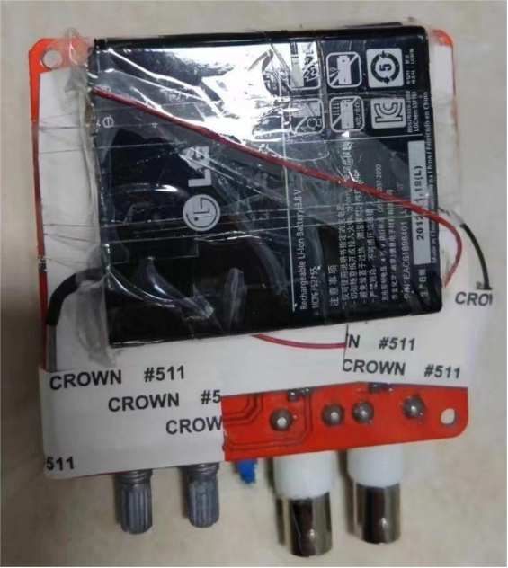
On the back, you can mount two phone batteries in series.
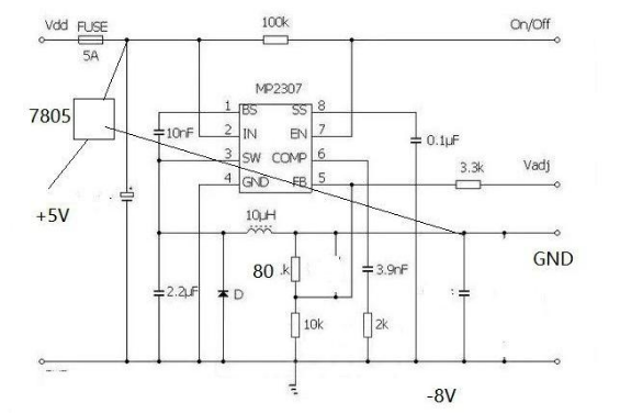
The 3R33 generates –8 V, the +8 V comes from the battery voltage, and the 7805 provides +5 V.
Once everything is wired up, test the voltages with a multimeter. If you read ±8 V and +5 V, then it looks fine—but there may still be problems later.
If issues come up, you can check with an oscilloscope.
The oscilloscope I used was a Puyuan DS5022ME. The question is: at what voltage does it actually power on? Slowly raise the adjustable power supply until it just turns on.
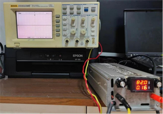
If the voltage is lower than that threshold, the screen just flickers and won't boot. At 82 V, the current is about 0.23 A (the meter wasn't accurate, add ~0.07 A), so the power consumption is around 19 W.
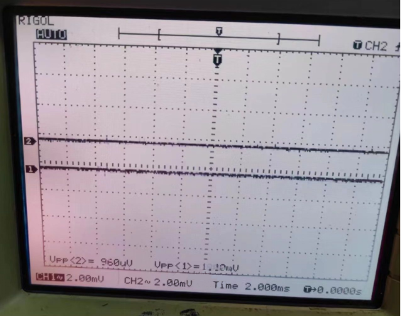
Here's the oscilloscope's baseline noise (with the probe clip and hook shorted).
Now you can test the DDS signal generator: at 1 MHz square wave, it looks decent.
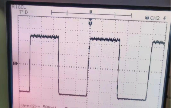
At 4 MHz square wave, still acceptable.
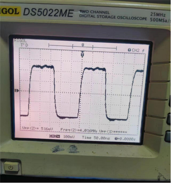
At 8 MHz square wave, if there's distortion, it could be an issue with either the DDS itself or the oscilloscope.
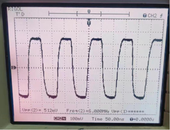
Here's a sine wave.
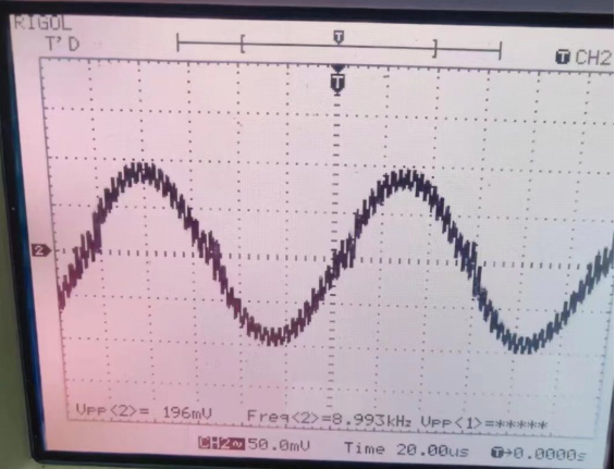
And here's a square wave as shown in the figure.
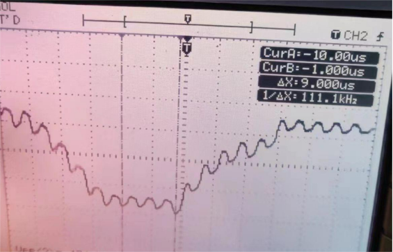
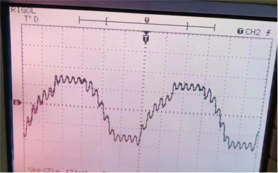
If you think the DDS output signal quality looks poor, try measuring the power supply ripple. Below is the ±8 V measurement.
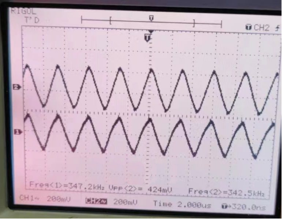
On the –8 V and +5 V rails, the 7805 shows much less ripple.
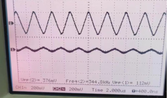
If you're still worried that individual 3R33 modules vary, you can test a few others. In my tests, they all showed pretty large ripple. These results are with capacitors added: 47 µF electrolytic and 0.1 µF ceramic on the input and output. No inductor was used.
Conclusion (for reference):
· The 3R33 can easily generate negative voltage.
· The 3R33 has a lot of ripple, and just adding capacitors doesn't reduce it much.


