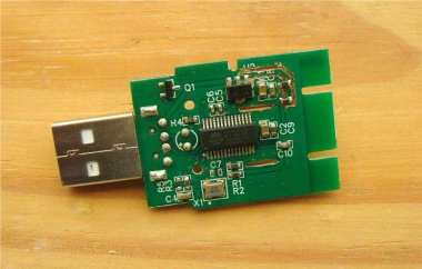
If you’re into DIY projects and want to revamp an old card reader, this article might be right up your alley.
As shown in the picture below, here's a really old-style card reader.
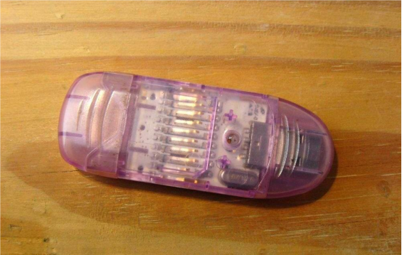
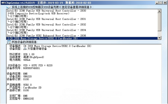
This reader can only handle SD cards under 2GB, and its main controller chip is the 6220.
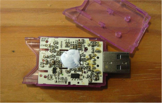
Once you open it up, the internal circuit board looks like this:
If you've got a similar old card reader lying around and want to upgrade it, you can use the AU6433 chip as a replacement, just like in this guide.
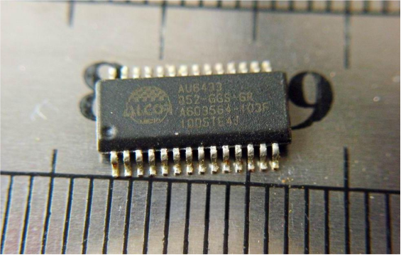
If you happen to have an old Acer laptop that's no longer in use, you can actually pull the AU6433 chip straight from its motherboard.
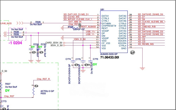
If you can't find the circuit diagram for the AU6433, try checking the corresponding section of the laptop's schematic—it might help you figure it out.
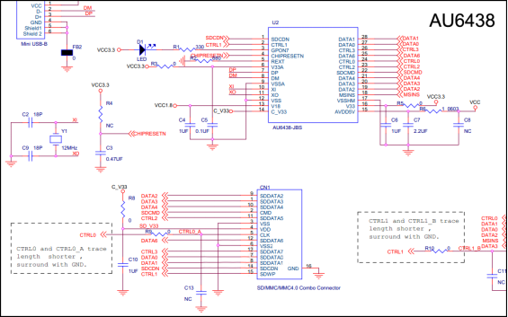
You can also refer to the schematic for the AU6438 chip as a reference.
Just keep in mind that the AU6438 and AU6433 are a bit different — the 6433 doesn't have an indicator light, and it was originally designed for laptops.
It runs using a 48M signal sourced from another chip, whereas the 6438 is a standalone version that uses a 12M crystal oscillator.
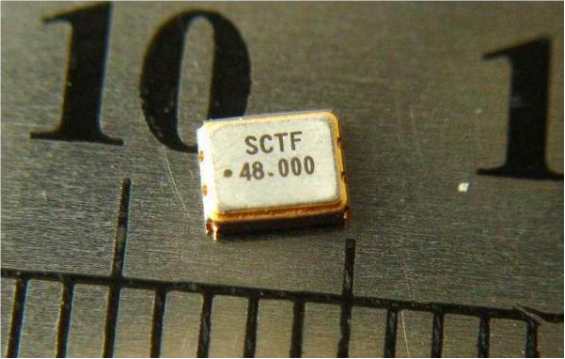
You can also make it work using an active crystal oscillator.
Here's a sample circuit diagram you can use for reference in your own design.
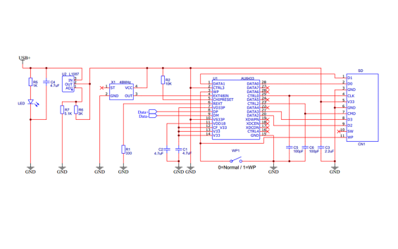
Next, you can draw your PCB layout based on the size of the original card reader.
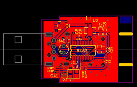
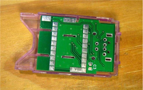
The back side looks like this:
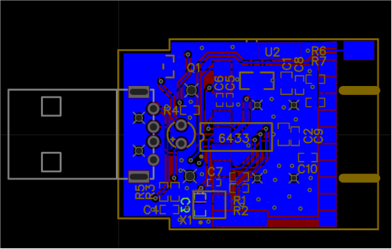
And here's a preview photo of how it should look.
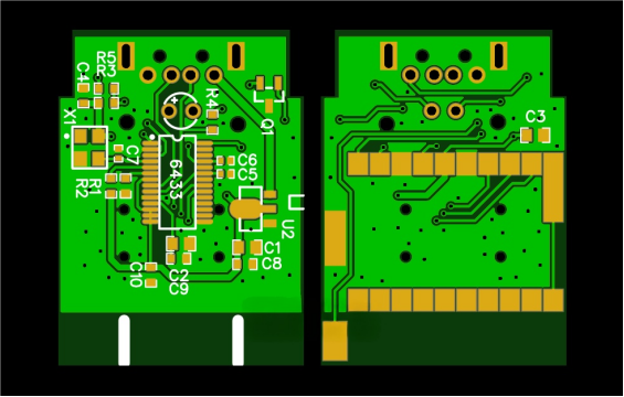
Once your PCB is printed, cut it to shape.
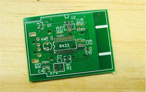
Then sand and smooth the edges so it fits nicely.
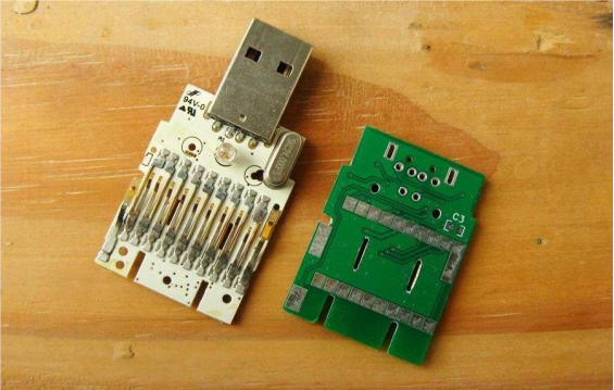
Now, place it back into the case.
Next, you can start soldering — begin with the crystal oscillator, IC, and LDO.
In the diagram, the LDO shown is a fixed-voltage type.
If you don't have a 3.3V LDO and only have an adjustable one, you can carve two small slots to install voltage divider resistors.
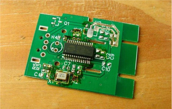
After that, solder all the external components in place.
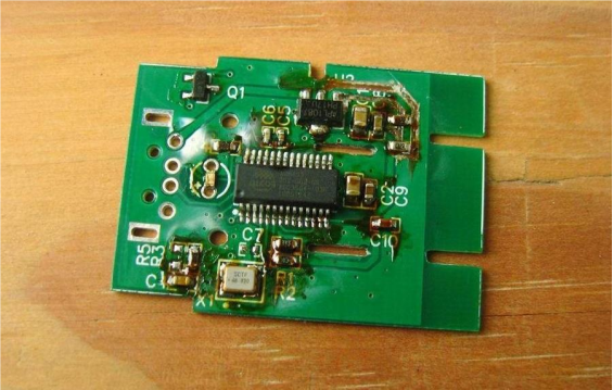
Do a quick test to make sure the device can be detected — if it is, you're good to go.
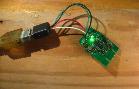
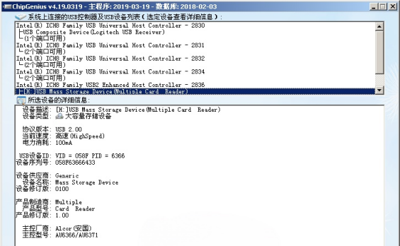
Then, make sure to solder all the metal contact clips on the back.
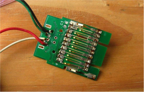
Once testing is done, you can fit everything into the casing.
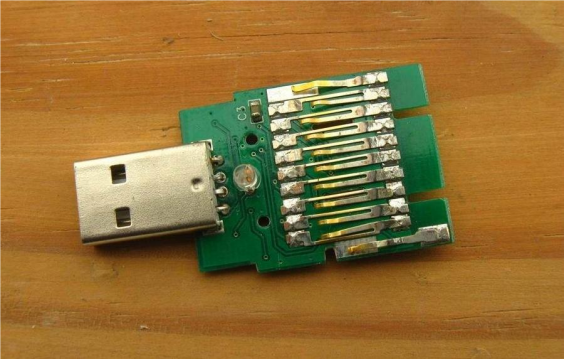
Clean off any leftover flux.
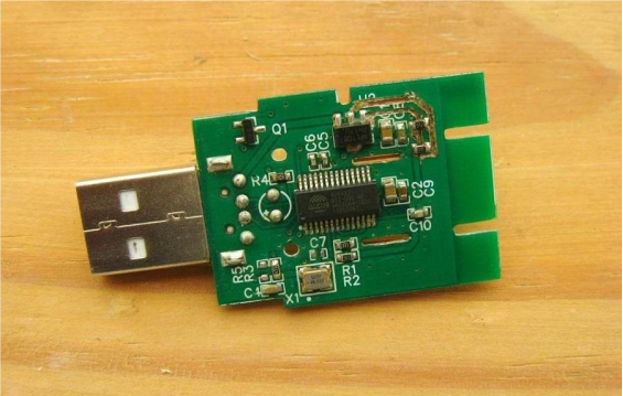
Finally, assemble it all back into the case.
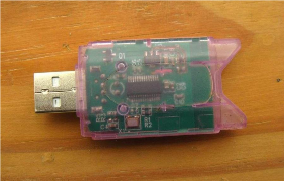
Done!


