
If you're interested in DIY speed control for an AUX remote-control fan, this article might be worth checking out.
The AUX remote-control fan has 3 speeds and 3 wind modes, but once it starts running, the motor noise is loud, the plastic housing vibrates, and the airflow feels harsh. The "wind mode" feature is basically intermittent blowing, which isn't soft at all. The noise doesn't really improve either, which makes it pretty uncomfortable to use on summer nights. So next, let's look at how to modify the fan to adjust its wind speed.
The fan is an AUX FS1605RC, 60W, and the whole unit looks like this in the picture below.
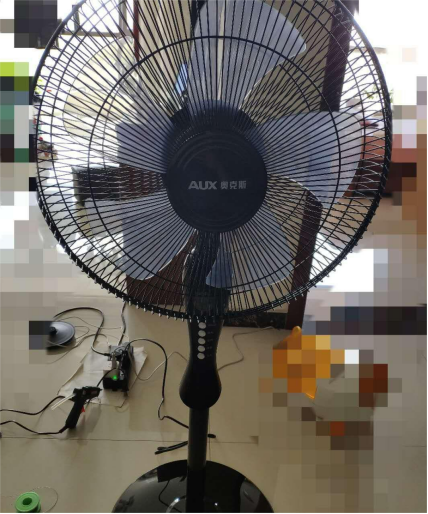
It looks quite compact—shorter than a typical floor fan but taller than a desktop fan. It blows directly toward the bed, which is just right. The panel layout is shown in the picture below.
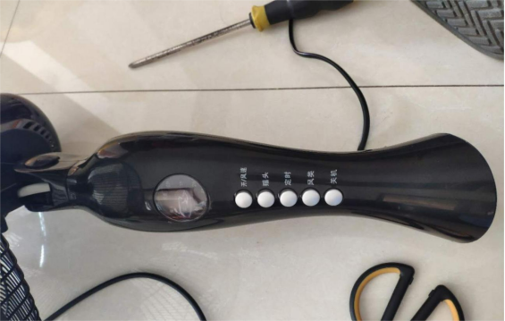
As shown above, the left side is the LED indicator that shows the fan's status. Moving right, you have Power/Speed, Swing, Timer, Mode, and then the Off button. Power and Off are two different buttons. It comes with a remote.
After taking it apart, the front side of the internal circuit board looks like this.
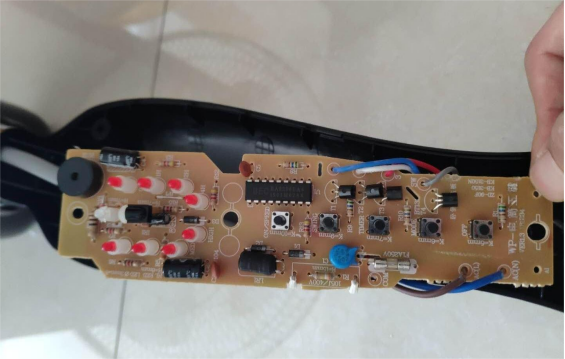
The markings are very clear. The black chip is model BEC BA8206BA4 / 1903m02a6.
The backside looks like this.
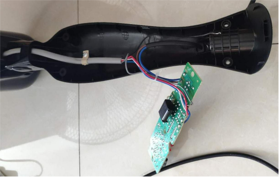
There's also a capacitor on the back of the circuit board, probably used for the wind-mode selection.
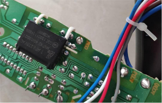
The capacitor model is 1uF J 275V AC, as shown in the picture.
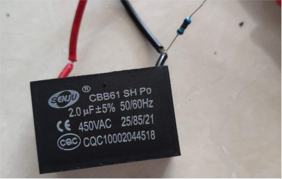
The motor's start capacitor is 1.5uF.
If this were a normal mechanical fan, the typical improvement method would be to parallel a CBB capacitor under 2uF with the timer, or add another capacitor with the same value next to the start capacitor, or place a 2uF capacitor in series on the L input line.
But be careful—adding a series capacitor to the power line may cause the fan to fail to start, or lead to abnormal remote-control behavior.
For this fan, you can choose to put a capacitor in series with the common terminal to reduce the speed. Conveniently, the circuit board labels everything clearly, and you just need to locate the COM point at the empty solder pad right below the capacitor shown above.
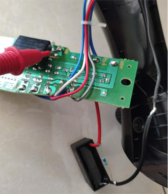
In the picture above, the red multimeter probe is touching the COM point. Temporarily connect a 2uF capacitor in series to test it. The speed improves noticeably—on low speed it becomes a gentle breeze.
Next, you can move on to the actual installation.
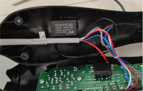
You'll need to solder everything securely, insulate it properly, and fix the capacitor to the deepest part of the housing using hot glue. Then close the cover. You can also drill a hole in the housing to install a toggle switch (letting you switch between the capacitor mode and no-capacitor mode, essentially giving you the fan's original 3 speeds and a softer 3-speed mode).
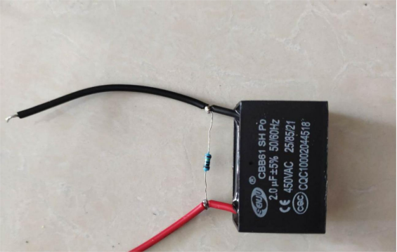
For the series capacitor setup, make sure to connect a 1MΩ resistor in parallel across the capacitor terminals for discharge. Otherwise, you might get shocked during disassembly or repairs.
After the mod, the remote still works normally, the fan speed is noticeably lower, and the noise is slightly reduced.
Done.


