DIY Digital Display Car Charger Modification Guide


If you are interested in DIY digital display car chargers, you may want to check out this article.
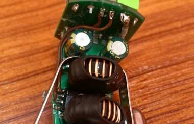
Suppose you happen to have two digital display car chargers, but after disassembling one of them, you find that the two USB ports are directly connected in parallel and share the same output circuit, which creates a potential safety risk. When one USB port enters fast charging mode with a high voltage output, the other USB port will also carry the high voltage. If a 5V device is connected at this time, it may be damaged. At this moment, you come up with the idea of combining these two car chargers into one and improving the design.
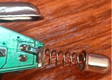
First, you add a surface-mount fuse to the input side. You also add a soft copper wire in parallel inside the positive spring, then weld the metal cap and spring together to reduce the wire resistance.
Next, you remove one car charger as a spare part, add the missing chip components to the other charger, and cut off the second USB port. You then connect the output positive line, DM, and DP lines with three wires to their corresponding pins. Only three additional components are needed, making the modification very simple.
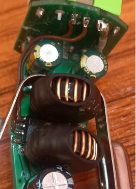
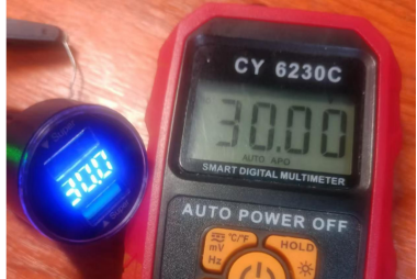
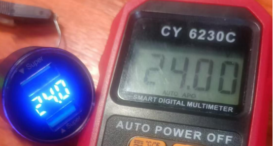
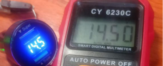
The original voltmeter display has an error of about 0.2V. Finally, you connect a 680K resistor in parallel with the R3 resistor. After modification, the actual measured voltage display becomes accurate. The project is complete.