DIY Mod: Adjust Mingwei LRS-200-24 Voltage


One piece of Mingwei LRS-200-24 switching power supply, with a nominal rating of 24V, 8.8A, and 211W.
The power supply adopts a fanless design and has a super slim appearance. The size is much smaller than the usual 200W power supply, especially in thickness, which is comparatively thinner. After testing, the temperature control of the switching power supply is good at around 200W power. The casing is a bit hot but not too hot to touch, and the output filter inductor generates a bit more heat, but the temperature control in other areas is good. This switching power supply does not use the common TL494 controller, but instead uses NCP1252E. According to the information, the efficiency of this power supply is more than 90%, which is very high without using a synchronous rectification scheme. This is also the reason why this 200W switching power supply does not use a fan.
Disassembly:
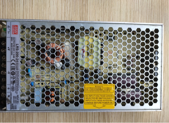
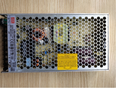
The power supply has a hexagonal honeycomb structure on the exterior casing.
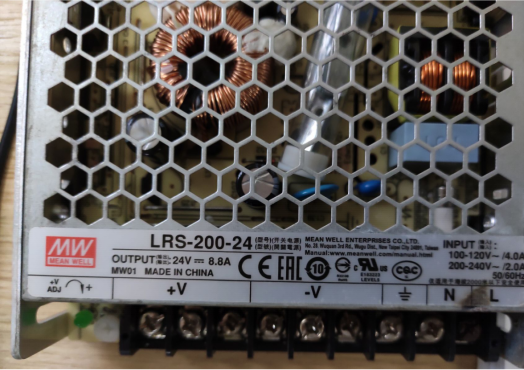
Nameplate parameters.
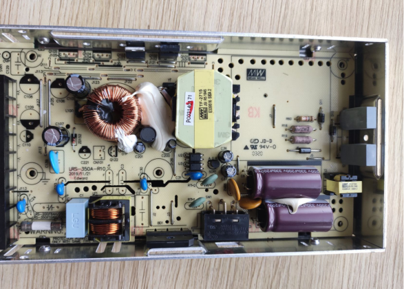
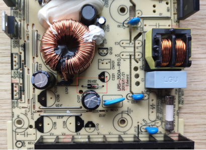
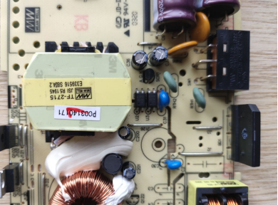
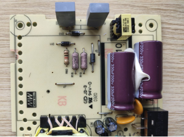
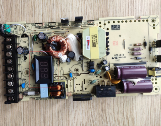
The front circuit design is relatively simple, with a lot of space between components, which is very conducive to heat dissipation.
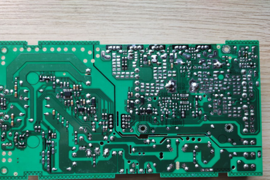
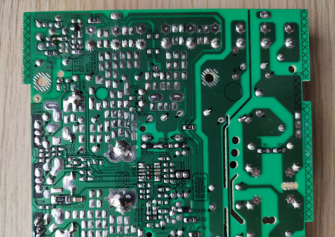
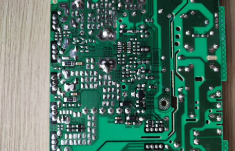
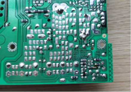
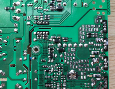
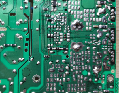
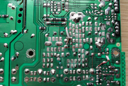
There are more SMD components on the back, and some areas are relatively dense.
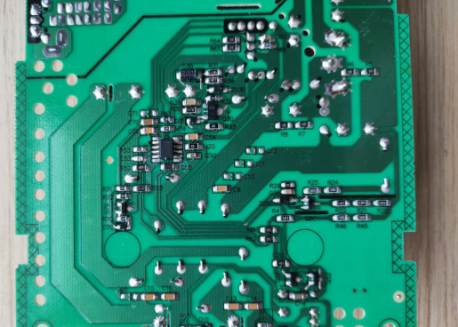
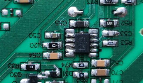
PWM main control chip NCP1252E.
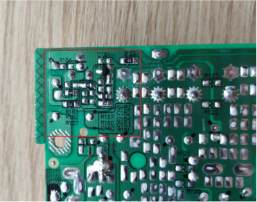
The red box is the voltage regulation circuit part.
Modification part:
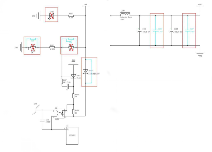
Schematic diagram:
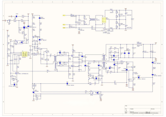
The following mainly shows the modified circuit diagram of the voltage regulation part and the output circuit:
The voltage regulation and 24V output circuit diagram is only a partial circuit diagram because this is only about modification, so other circuits can be ignored. This switching power supply itself has the function of fine-tuning the voltage, but the voltage adjustment range is quite limited, only a few volts up and down.
If the original adjustable potentiometer on the motherboard is directly replaced, it cannot achieve a large range of voltage regulation. After testing, the voltage can only be adjusted down to 17V at the lowest after replacing the potentiometer. The original circuit has an overvoltage protection of about 30V, and the voltage resistance of the low-voltage capacitor is 35V. Therefore, considering factors such as circuit design, core saturation, duty cycle, and capacitor voltage resistance, it is better not to modify the overvoltage protection value.
The specific modifications are as follows:
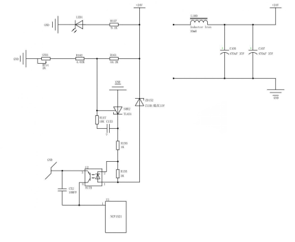
Modification Diagram
2.5V-30V voltage regulation circuit.
1. Remove the LED light-emitting diode and power indicator LED1.
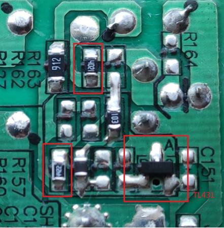
2. Remove the R61, 44.2K resistor and replace it with a 50K adjustable resistor.
3. Remove the SV21, 4.02K resistor and replace it with a 470Ω resistor.
4. Short-circuit the ZD152 diode with a wire.
5. Add a polyester capacitor C105' of 0.1uF after capacitor C105.
6. Add a polyester capacitor C107' of 470pF after capacitor C107.
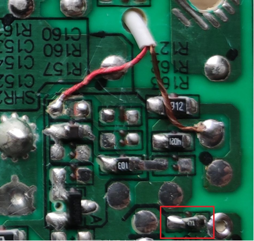
Location of the resistor to be removed is indicated in the red box.
Location of the voltage stabilizing diode.
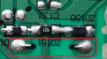
Location of the voltage stabilizing diode that needs to be short-circuited, indicated in the red box.
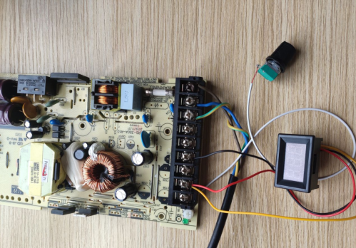
Solder the potentiometer and voltmeter.
Debug the circuit.
Secure the voltmeter and potentiometer.
Assemble the casing.
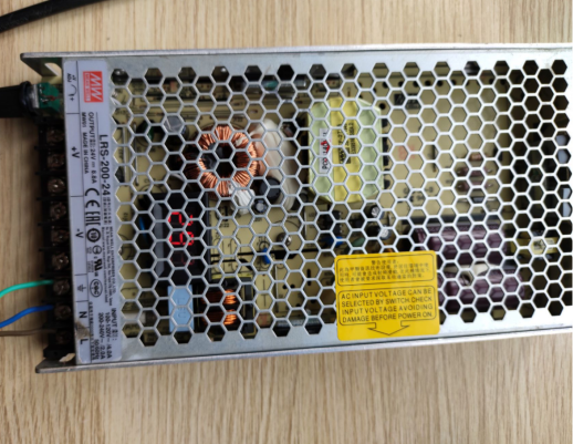
Test with power on.
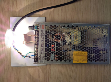
Load test with a 50W load.
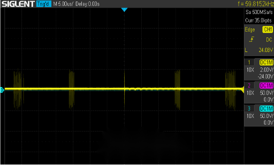
Finally, check the output waveform, with ripple range of around +/-2V and relatively smooth voltage. It has been tested that adjusting the voltage up or down has little effect on the waveform. This is the waveform under a 50W load.


