DIY Power Supply Modification Guide


If you encounter problems while modifying your power supply or are new to power supply modification, you can check out methods and experiences that may be suitable for you and the tools you need to prepare.
Tools required: Electric soldering iron, of course, soldering station is better, with a higher power if possible; high-quality solder is necessary; Only rosin flux should be used, other fluxes and soldering pastes should not be used (these two are conductive, which can cause the circuit parameters to fluctuate and the cause can not be found); you will need a pair of pointed nose pliers, a cross screwdriver, a pair of pointed pliers, a solder sucker and the skills to solder components the size of sesame seeds onto the circuit board.
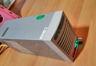
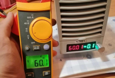
Here are some experiences with modifying a 60V 50A power supply:
1. Power supply disassembly: When disassembling the power supply, do not use too much force to remove the screws, otherwise, the screws may be damaged and unable to be reassembled. When removing the EMI filter board and the control board, be gentle. There are two fixed screws under the control board with connectors underneath. After removing the screws, gently shake the board up to remove it easily. If you cannot remove it, check which step went wrong, whether the screw was not removed, or there is a problem somewhere else. Do not use too much force and damage the connector or the board.
(Note: Do not use tools such as pliers to disassemble, use your hands directly. Tools such as pliers may damage the components or traces on the circuit board, causing more harm than good.)
2. Disassembly of components on the control board and soldering: When disassembling components, the temperature of the electric soldering iron should not be too high, 280 degrees is enough. Before starting, double-check the position and number of the original component, and do not disassemble the wrong component. Pay attention to your soldering iron head, do not touch other components or remove them by mistake. After each component is removed or the wire is soldered, check carefully to see if the solder joint is connected or if other components have also been removed. If you are using a small OLED screen or other kit, there may be many colors of ribbon cable in the kit, and some colors are easy to confuse. When soldering, double-check the color of the wire and the solder joint. After soldering, clean the solder joints with a PCB cleaning solution.
3. Precautions and experiences for opening holes on the front panel and installing the rear panel: When opening holes on the front panel, be sure to align the position of the sticker. When opening holes, be gentle. If too much force is used, the panel may be damaged. After opening the hole on the mesh, it is best to polish it and wrap the opening with tape because it may cut or break the wire. When installing the rear panel, match the length of the wire. The space is narrow when installing the side panels, so do not make the wires too long, or they may not fit. When soldering the connectors or banana plugs, you can increase the temperature of the soldering iron a little, but do not heat them for too long, or the plastic of the plugs may melt. After soldering, check for any dry solder or open circuits. One more thing, make sure to use sufficiently thick wires. For a 60V 50A power supply, it is recommended to use 6 or 8 square soft silicone wires, and buy national standard thickened terminal blocks.