DIY: Boost Your Fly Swatter to 2500V Power


Lead-acid battery is damaged and replaced with a lithium battery, but it often fails to kill flies instantly due to voltage drop as the battery discharges, even though the lithium battery provides greater power than the original lead-acid battery (as the latter has higher internal resistance and voltage drop during operation), sometimes requiring multiple consecutive strikes to be effective, it may be worth considering a modification to increase its effectiveness.
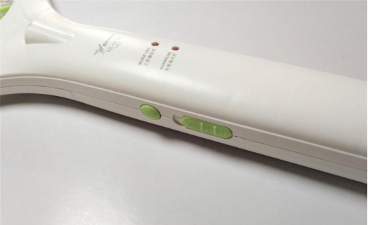
It has two modes: one without illumination and one with illumination. This modification will convert it into a single-mode with continuous illumination.
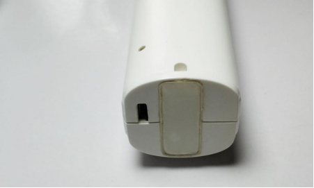
Since the previous modification of the charging circuit for the lithium battery rendered the original lead-acid charging circuit obsolete, a micro USB charging port was added at the rear, with the small hole serving as a charging indicator.
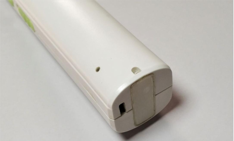
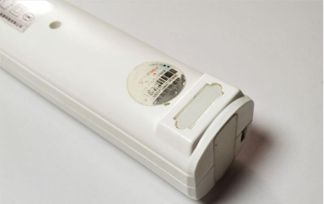
The original 220V plug was also removed, and the plug and plastic spacer at the rear were homemade.
Opening it again...
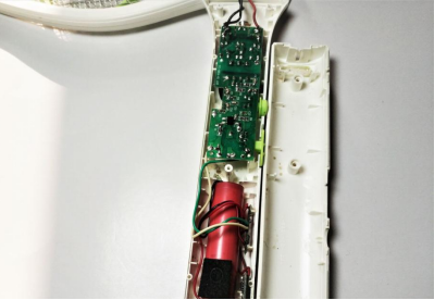
An extracted 18650 battery cell and a 4056 charging circuit were used.
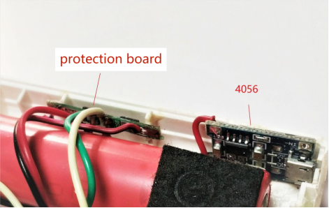
Circuit board.
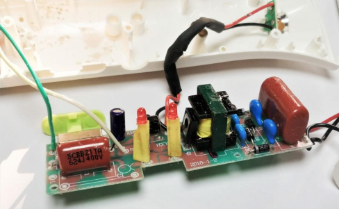
The overall design involves boosting the voltage in the first stage, followed by rectification to achieve four times the voltage, and then outputting it through a larger CBB capacitor to enhance load capacity.
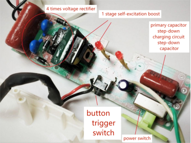
The simplest way to increase the output voltage is to raise the input voltage. Since the device is battery-powered, adding a boost stage in the middle will suffice. Let's first check if the voltage rating of the capacitor used for the voltage multiplication and rectification is sufficient, which it appears to be.
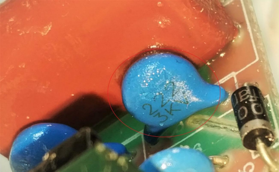
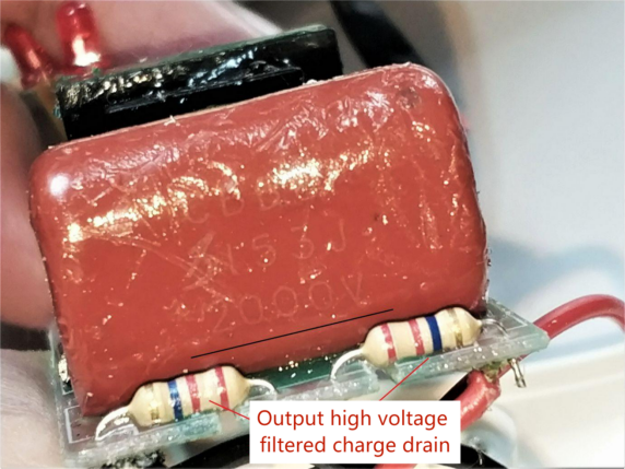
Next, let's examine the output filtering at the final stage. The voltage rating is only 2000V, which is somewhat low. However, CBB capacitors generally have a significant voltage margin, so a margin exceeding 50% should be acceptable.
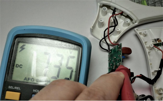
Now, let's measure the actual voltage of the 1x capacitor used for voltage multiplication. It reads 735V.
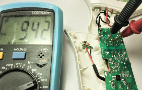
For the 2x capacitor, the voltage is only 942V, indicating that the oscillations of the first-stage self-oscillating circuit are asymmetric, with the negative half-cycle output significantly lower than the positive half-cycle by approximately 207V (942V - 735V). Therefore, when powered by a lithium battery, the electric mosquito swatter's maximum output voltage is approximately 2000V (considering the input impedance of the multimeter, the actual output will be slightly higher than the measured value of 942V, approximately 1900V).
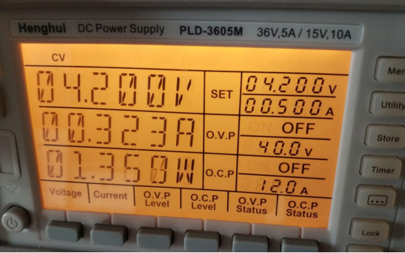
Let's measure the static and operating currents: approximately 320mA at 4.2V (the maximum voltage of a single lithium battery). The power output is limited, and there is a limited increase in current during operation.
You can raise the input voltage to around 5V, increasing the static current to approximately 390mA, with the operating current not exceeding 500mA.
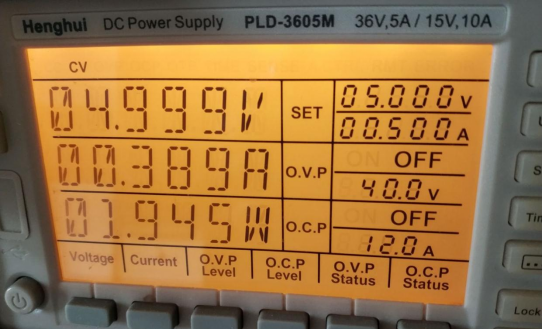
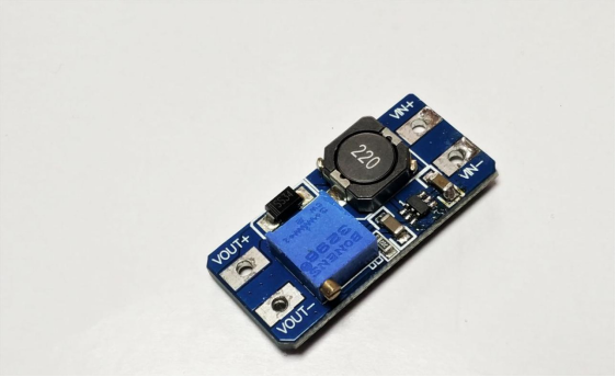
Therefore, using an inexpensive boost module will fully meet the requirements.
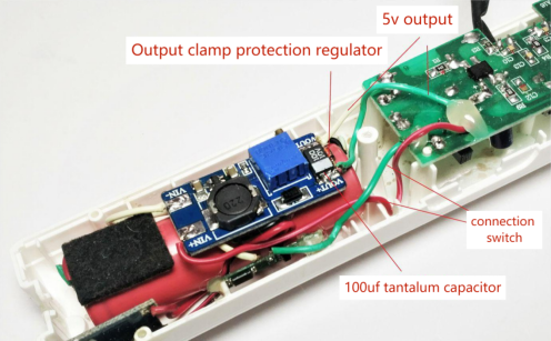
As the device operates in a high-voltage environment, it's inevitable that some high-voltage induction or coupling will be introduced. Thus, a voltage clamp protection using a regulator diode of approximately 7V (to prevent potential issues if the regulator diode is absent) and a parallel tantalum capacitor are added to enhance the transient load capacity of 5V and further suppress any induced high-voltage feedback. The modification is straightforward: remove the original circuit connections, cut the necessary traces on the PCB, and wire the boost module in the middle, with the original switch controlling the battery and boost module input.
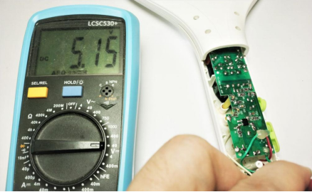
After soldering, adjust and measure the output of the boost module, which reads around 5.15V, a suitable value as going too high could compromise the voltage withstand capability of the CBB capacitor in the final stage of the electric mosquito swatter, and the original discharge gap may not adapt to higher voltages, causing it to fail to zap mosquitoes and potentially break through.
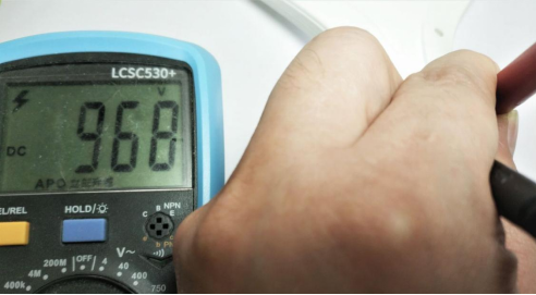
When the input is at 5V, measure the actual voltage of the 1x capacitor, which reads approximately 968V, indicating a roughly 30% increase. Therefore, the negative half-cycle also experiences a similar 30% increase, resulting in an output of around 269V (207V x 1.3). Consequently, the actual voltage of the 2x capacitor is approximately 968V + 269V = 1237V (note that the 2x capacitor exceeds the range of a multimeter, so this is an estimation). Therefore, the final stage's 4x voltage boost outputs an actual voltage of approximately 2500V, an increase of around 600V compared to the original voltage.
Finally, secure the plastic piece at the rear, and after testing, it's evident that the power has significantly increased without any decrease across the full range of battery voltage (from lowest to highest).
Feel free to try this modification yourself and observe the actual results.


