DIY Electric Screwdriver with N20 Motor


If you're tired of twisting screws, then let's make a small twisty screw together.
Components: N20 geared motor + coupler + screwdriver bit connector + lithium battery + control circuit + whiteboard pen shell.
Components to purchase online:
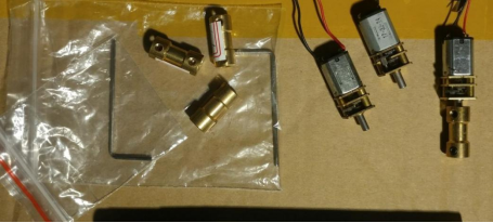
The N20 geared motor with a 3.7V and 145 RPM reduction ratio is suitable for the requirements. The coupler is a 3mm to 5mm model. Design the control board: a simple lithium battery charging circuit and an L9110s H-bridge driver.
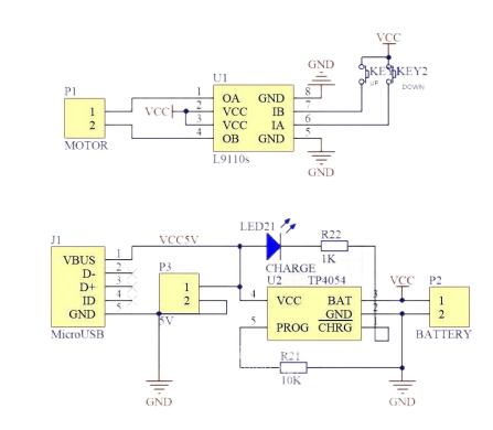
Since the motor needs to rotate in both directions, an H-bridge driver is required. The L9110s operates in a voltage range of 2.5V to 12V and can be used with 1 to 2 lithium batteries. The maximum current is 800mA, but we only require a very small current, around 70mA during normal operation and less than 200mA when stalled. Therefore, it's completely suitable. The most important aspect is convenience in control, and one chip is enough to handle it all. Additionally, the static power consumption of the L9110s is very low, to the point where it can be disregarded, so there's no need for any power switches. The setup is kept simple with just two buttons: one for forward rotation and the other for reverse rotation. We don't use a directional switch since it would be inconvenient to switch it back and forth every time. In our testing, a single charge lasted for more than two months.
For charging, we can use the TP4054. The original components from the POS can be transferred to the new setup, with a charging current of 100mA. Slower charging is acceptable as it increases the battery lifespan. Since my usage rate is not particularly high, longer charging times are not a problem.
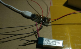
PCB: MicroUSB direct plug-in for charging. It includes a charging indicator light that is on during charging and turns off when fully charged. The U1 pin is the common point for the buttons, and the other two pins below are connected to the forward and reverse buttons. The two rightmost pins are connected to the motor.
For thermal transfer printing, select the monochrome option. A constant temperature electric iron with a cotton or linen setting is used for thermal transfer printing. Apply pressure for about a minute to achieve satisfactory results. The image attached has already been printed and coated with resin and solder. Although the overall board with solder may not look great, it provides protection against oxidation. The L9110s and charging chip are located beside it.
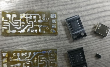
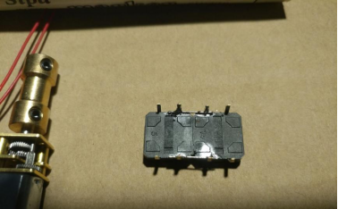
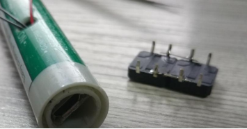
Below is another version of the control board made using discrete components and thermal transfer printing.
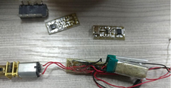
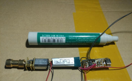
The batteries are connected in parallel since the motor is not suitable for high voltage, and it's also inconvenient for charging. Two batteries are used not for current or endurance reasons but because the shell can accommodate two batteries perfectly. Since the current is very small, using thinner wires is acceptable. Both the charging and control have been tested and are working fine. The control board is good to go.
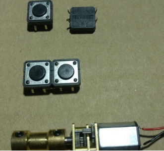
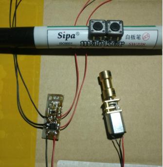
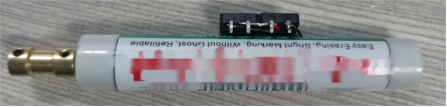
The image shows the motor connected to the coupler and the buttons. The larger buttons provide a good tactile feel and are easy to use.
The two buttons are connected by their resistor legs.
Then they are attached to the shell like this.
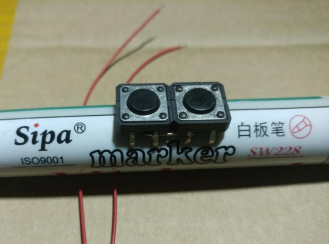
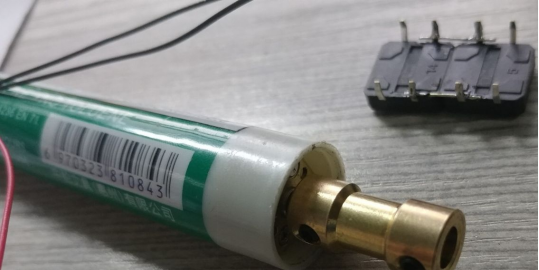
The shell used is from a whiteboard pen, with the inside hollowed out. Its outer diameter is 17mm, making it a perfect fit for the N20 motor. The circuit board is connected to the motor, and the remaining wires are connected to the battery and buttons.
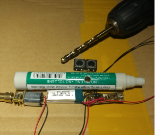
Organize all the components and compare them with the size of the shell to ensure they fit perfectly.
Let's start the final assembly. It's basically putting everything inside the casing.
First, make a hole on the casing. This is for the wiring of the buttons to come out. The size of the hole doesn't matter because the buttons are large, and they can be covered by button caps in the end.
The position for the hole is determined here. It's comfortable to hold the device with one hand in both normal and reverse grip.
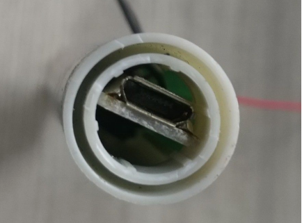
Trim the end of the pen tip. The motor is the largest component, so it should be placed at the tail end of the pen where the opening is the largest. There are some grooves inside where the motor can fit snugly.
Next, insert all the internal components shown in the previous diagram. Let the wires of the buttons come out.
The original pen tip (now the tail end) has a slightly smaller inner circle after trimming. Adjust the control board to fit tightly within this inner circle.
Here's a little trick: slightly flatten the pen casing, then insert the charging port section. When you release your hand, the circuit board of the charging port will fit tightly in that position. If you want extra stability, you can apply some hot glue to secure it.
From the side view, create a slight recess to protect the charging port. After all, when holding the device in the reverse grip, the thumb needs to rest on this position. If it's flush with the outer surface, it might feel uncomfortable when pressing.
On the other end: use the same method of flattening the casing to insert the N20 motor.
From the side view, the motor should also be recessed. This way, it will be securely fixed and provide good protection for the gear set. If you need extra stability, you can apply some hot glue here. If not, it will be easier for future maintenance or disassembly.
Finally, solder the buttons in place.

Based on the actual motor rotation direction, adjust the placement of the buttons. Pressing them should rotate clockwise, while lifting them should rotate counterclockwise, following the common logic of user interaction. Once you've adjusted the button positions, use hot glue to secure them in place. The buttons should sit on top of the casing perfectly.
You can either stuff the excess wires into the casing, cut them shorter, or coil them beneath the buttons. It's best not to cut them because if you do, you'll need to re-solder longer wires to pass through that hole when you disassemble it next time.
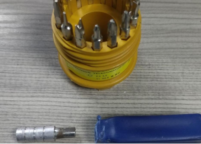
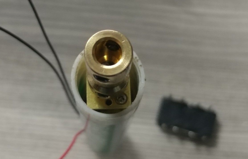
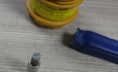
The diameter of the rod end is approximately 5mm. With a little polishing, it can be inserted into a 5mm hole of the coupler. Furthermore, the chuck head has a magnet inside its inner hole, making it convenient to quickly change chuck heads. It uses a standard 6-sided interface and can directly work with the 22-in-1 blade from the Digital House.
If you're not concerned about quickly changing chuck heads, you can insert the chuck head directly into the coupler and secure it. The 5mm coupler is a bit thick for direct insertion of the chuck head, so you can wrap some paper around the tail end of the chuck head before inserting it. The coupler is secured with symmetrical double-threading, ensuring the stability of the chuck head.
With the South Flag 10-in-1, simply insert the blade into the rod to use it. It's a perfect match with 100% compatibility. The only regret is that the South Flag 10-in-1 blade doesn't have a magnet. The 22-in-1 blade works perfectly.
There are two versions, including a first-generation prototype.
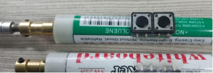
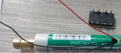
Charging in progress for the second device.
Charging in progress for the first device.


