DIY Supercapacitor Car Jump Starter with LT8705 Module


If the remaining materials from the spot welding machine are used to create a car emergency power supply, the capacitance is large, and charging and discharging cannot be done through the same port, among many other disadvantages. However, a more portable and safer approach can be taken: using a supercapacitor to make a car jump starter. The shell used measures 250*80*85.
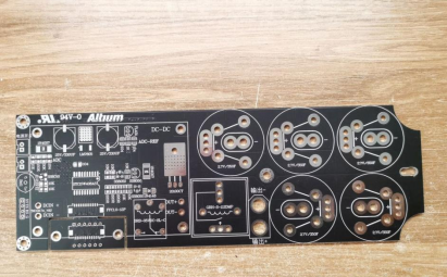
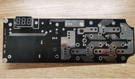
The board has two corners with internal arcs that fit perfectly inside the shell, utilizing the fixed holes provided by the shell.
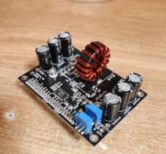
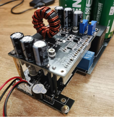
A homemade LT8705 module is used for automatic voltage regulation, which is compact and efficient.
Since this board is designed with a common ground, only switching the positive pole can achieve charging or discharging through the same port. The relay used is an Omron GRH-S112DMP.
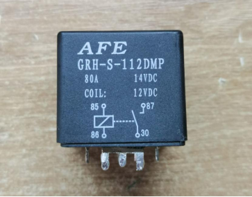
During testing, the contact resistance of the relay varies and is not constant, which may be caused by burrs on the relay contacts.
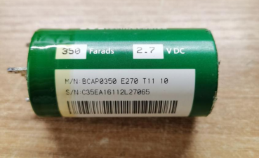
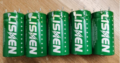
For the Farad capacitor, a dismantled 2.7V/350F capacitor from LiShen is used, and the board is also compatible with China Railway's supercapacitors. The basic information and labeling of the capacitor are provided.
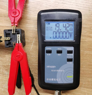
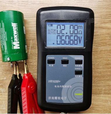
The internal resistance of the 310F capacitor should be better than that of the 350F capacitor, but the measured internal resistance of this capacitor is around 2mΩ, which is strange.
Five capacitors are connected in series, and their internal resistances are generally consistent.
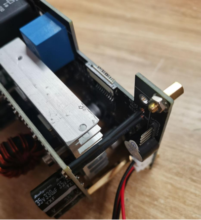
The board is still designed with a double-layer layout, with the automatic voltage regulation module placed on top and the control circuitry below. The display board can be detached and connected to other parts using a ribbon cable.

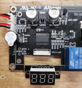
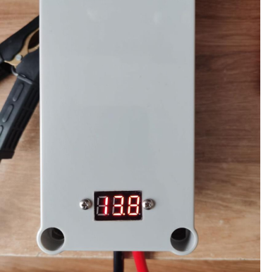
The digital display is designed on the back of the board, showing voltage, ignition countdown, and other information. Each capacitor is equipped with a 1K resistor as a discharge resistor. If the capacitor is fully charged and not used, it will be completely discharged in about two days. It can be charged on-demand, avoiding long-term storage with residual charge and voltage imbalance. Therefore, the balance circuit can be eliminated.
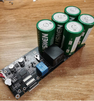
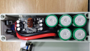
With the capacitors and relay installed, as 5 capacitors have a larger capacity than 6 capacitors, the discharge time can be increased. Additionally, the internal resistance of the 5 capacitors is smaller than that of the 6 capacitors, which enhances the instant discharge capability. The datasheet indicates that the maximum voltage withstand of the capacitors is 2.85V. 5*2.85=14.25V, which fully satisfies the car's starting voltage.
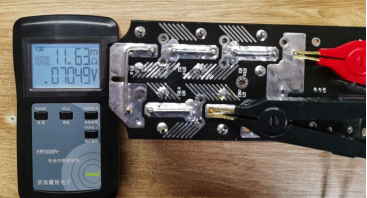
The internal resistance of the capacitor bank is 11.63mΩ.
The display part is detached, and holes are drilled in the shell.
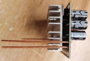
Two copper columns are installed to adjust the height, aligning them perfectly with the shell.
The output voltage of the automatic voltage regulation module is pre-adjusted, and fine-tuning will be done after installation.
Four 2.5-square hard copper wires are soldered to the automatic voltage regulation module for electrical connections.
Heat shrink tubing is applied to the copper wires, and the heat sink is placed close to the charging relay.
Copper columns are installed on the board. Originally, four could be installed, but since the four copper wires are already securely fixed, two are omitted.
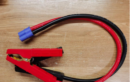
6AWG wire, approximately 14 square millimeters, is used for the output line. An EC8 aviation model plug is soldered.

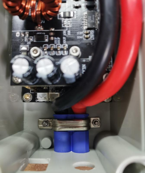
An old instrument's fixing buckle is used to create a device to secure the EC8 plug. It fits perfectly, with ideal dimensions.
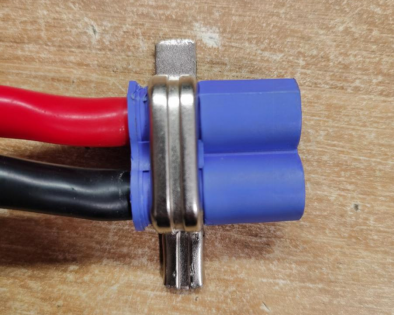
The EC8 plug is firmly secured to the shell and does not wobble.
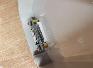
The display ribbon cable is made of FPC soft flat cable.
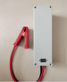
Overall appearance:
Let's make a charging clamp as well.
Speaking of charging, since this the power source can only handle a maximum current of 5A, the input module switches to MPPT mode.
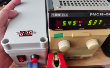
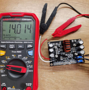
Due to the presence of a reverse current protection diode on the board, the output voltage of the module needs to be adjusted to 14.7V in order to charge the capacitor to 14V.
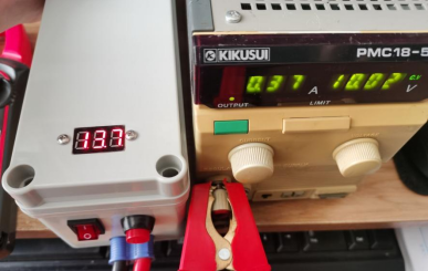
Charging is complete, taking 6 minutes from 0 to 14V. Of course, this is limited by the power output of the power source. If using a battery for charging, it would probably take around 3 minutes.
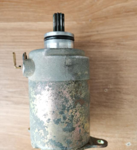
I tested it with the starter motor of a pedal motorcycle. The current could reach 40A at the moment of starting, but once it starts running, the current drops to only 14A.
As for whether the starting current is sufficient, let's take the Volkswagen starter motor as an example. With a power of 1.1KW, the starting current at 12V is approximately 92A. On the board side, the internal resistance of the capacitor is 12mΩ, the relay resistance is 20mΩ, and considering other miscellaneous wires, the total internal resistance of the starter motor is about 100mΩ. So, with 12V/0.1Ω = 120A of current, it can definitely start vehicles up to 2.0L on its own.


