DIY Spot Welder with STC MCU & Auto Modes


Spot welding machines are something you can do without, but you can't be without them either. A self-designed spot welding machine is definitely more handy to use than a purchased one, and the best part is, it saves money. Here's the layout of a well-made PCB:
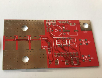
PCB dimensions: 90*50mm
The actual colors may not be as vibrant as shown in the software.
The MCU used is the 20-pin STC8H1K08, which comes with a cheap and reliable 10-bit ADC. The MOSFETs used are 4N04R8, with 6 on the front side and 3 on the back side. The 6 MOSFETs theoretically support 1800A, and with properly configured capacitors and the welding pen, they are more than sufficient. The first board only used 4 MOSFETs, which was enough for spot welding. Considering the thin circuitry on the PCB, the current is divided between both sides.
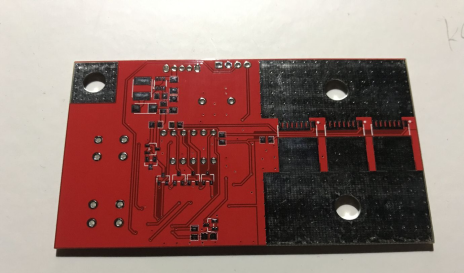
Optocouplers are used for input detection, and the SX1308 boosts the voltage through controlled circuitry for driving the 4N04R8. The boost circuitry is designed on the back side of the circuit board. The 6 4N04R8 MOSFETs are wired with equal lengths, and each MOSFET gate has a resistor. So far, in the two boards used, there hasn't been a single case of MOSFET blowing.
This time, a three-digit LED display is used, adding many functionalities.
The main features include:
1. 30 automatic welding levels - no need to configure pulse parameters, just select the desired level for spot welding.
2. In cases where the automatic level is not sufficient, you can switch to manual mode and configure three pulse parameters: adjustable pulse width from 1 to 99ms, adjustable pulse interval from 0.1 to 9.9ms, and adjustable pulse count from 1 to 99 times. This is convenient for various thicknesses of connection pieces.
3. Power supply voltage display, allowing you to monitor the spot welding output voltage in real-time.
4. Spot welding count recording.
5. Option to set whether the buzzer makes a sound during key presses or spot welding.
6. Restore to default settings.
7. Automatic saving of pulse parameters, so you don't have to reset them every time you power on. As long as you don't restore the default settings, both the automatic mode and manually configured parameters will be stored, and the data will not be lost when switching.
8. Adjustable welding trigger delay.
9. Automatic shutdown.
Here's an image of the finished product.
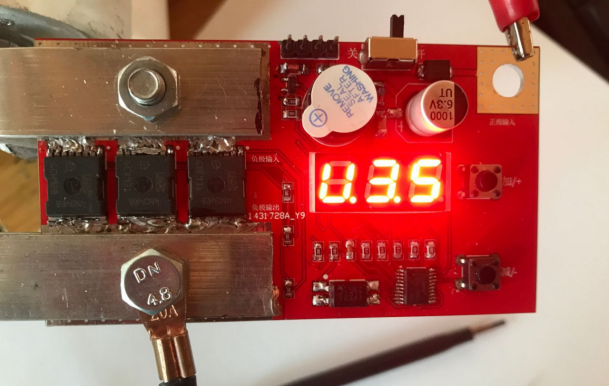
When it comes to capacitors, it's important to note that commonly used capacitors for spot welding machines are usually rectangular capacitors from Korea and cylindrical capacitors from the United States. The cylindrical capacitors have a higher internal resistance, and if used alone, outputting a large current may damage one of the capacitors. However, if two sets of capacitors are used together, there won't be any issues. Rectangular capacitors are considered to be better, but they are more expensive. After all, buying four cylindrical capacitors is still cheaper than two rectangular ones.
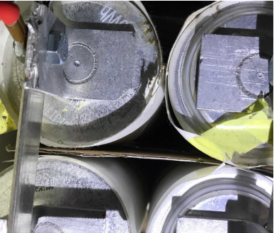
For capacitors connected in parallel, copper bars are used.
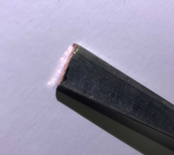
These are 2*15mm copper bars. The same copper bars are used for current collection on the PCB. We only need 4 pieces of 40mm length for the capacitor connection.
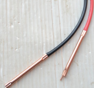
The spot welding pen used is a ready-made one with 10AWG wire.
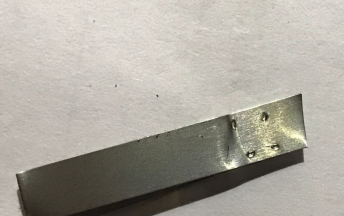
Stack two pieces of 0.15mm nickel plating together for a 3ms double-pulse spot welding, and use the highest priority timer for output timing.
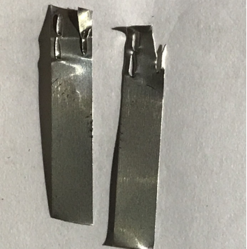
Each weld point is secure.
First page menu:
Functionality of the two buttons: Button '+': Short press on the default page to enter the menu selection page; long press on the default page to reset the spot welding count to zero; short press on the menu page to cycle through the menu options in order; if you switch too far, you can long press this button to return to the previous menu; on the parameter configuration page, short press to increase the parameter value. Button '-': Short press on the default page to toggle between voltage and spot welding count display; short press on the menu selection page to confirm the menu selection; after entering the parameter configuration page, short press on this button to decrease the parameter value; after adjusting the parameters, long press this button to return to the menu selection page. In the case of automatic shutdown, either of the two buttons can wake up the system.
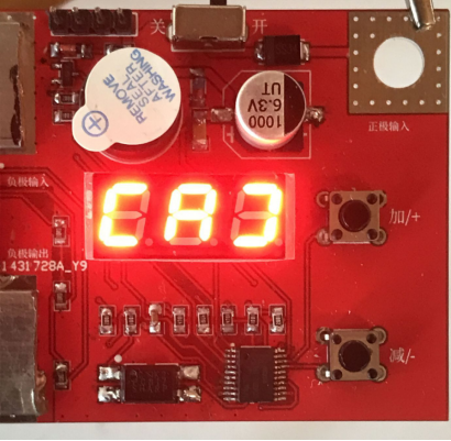
When in the automatic mode menu, the display shows [A].[d].[E].[F].[U].[H]:
[A]: Menu page setting for spot welding levels, ranging from 1 to 30.
[d]: Menu page setting for the welding pen trigger delay time, ranging from 0.5s to 3s.
[E]: Setting for the buzzer output, allowing for options such as output during spot welding, output during button presses, simultaneous output, or no sound.
[F]: Setting for the automatic shutdown delay, adjustable from 1 to 30 minutes.
[U]: After modifying the parameters, automatically return to the settings.
Options include:
1. Automatically return and display the voltage;
2. Automatically return and display the spot welding count;
3. Automatically return and turn off the digital display;
4. Don't automatically return.
[H]: Switch between automatic mode and manual mode, and restore default parameters. Enter "33" with the two buttons to switch between automatic and manual modes, and enter "66" to erase all the set parameters and restore the default settings.
When in manual mode, the display shows [A]..[C].[d].[E].[F].[U].[H]:
[A]: Setting for pulse width parameter, ranging from 1 to 99ms; setting for pulse interval parameter, ranging from 0.1 to 9.9ms.
[C]: Setting for pulse count parameter, ranging from 1 to 99.
The rest of the options are the same as above.


