DIY High-Precision GPS Clock Calibration


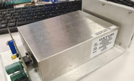
If you happen to possess two DATUM LPRO rubidium atomic clocks and also have a DAQ system called BigPulse O22B, along with two frequency counters, but all calibrated repeatedly to 10MHz.
Both machines are calibrated using TimeACC07 and TimeCatcher1588, which are GPS-disciplined rubidium clocks that output at 10MHz, and their accuracy is generally satisfactory. Refer to the attached diagram.
Simplified calibration principle: Utilizing the long-term stability of GPS by taking multiple averaged measurements, which aligns with the concept of GPS-disciplined oscillators (GPSDO), without the need to purchase an additional GPSDO. Although the GPS PPS signal fluctuates by ±20ns, it remains consistently accurate over the long run, and averaging multiple measurements ensures precision.
Some individuals have implemented the GPSDO principle using microcontrollers. The microcontroller operates a counter and interrupts, utilizing two consecutive PPS interrupts to count the cycles of the disciplined crystal oscillator. Theoretically, there should be 10 million counts in one second. By averaging the counts over multiple seconds, the theoretical accuracy becomes 1/10 million, approximately at the -7 level. However, considering factors such as the uncontrollable nature of microcontroller program execution, it becomes even more challenging to guarantee precision. Using an FPGA might alleviate some of these issues. Another method of disciplining involves employing a Time-to-Digital Converter (TDC) chip. It is possible that the mentioned TImeACC007 device follows a similar approach, precisely measuring the deviation between the local clock and GPS PPS and using the average deviation for disciplining. The accuracy of this method surpasses that of microcontroller-based counting. However, such devices are likely to be more expensive and not suitable for amateur enthusiasts.
There is another relatively affordable calibration method that only requires the following:
1. A reliable GPS module such as LEA-M8T with an outdoor antenna.
2. A frequency counter such as 53131A/132A/181A, or any other device supporting serial communication and capable of connecting to a computer for data retrieval.
3. The clock to be calibrated, whether it is TCXO, OCXO, or a rubidium clock. Ordinary crystal oscillators are not recommended as their precision does not offer significant value for this calibration.
This method offers high precision. With the 53132A frequency counter, which boasts a precision of 150ps, achieving -9 accuracy for a 1-second interval is more than adequate, even if the 53131 page mentions a precision of 500ps. Specialized TDC chips provide precision in the tens of picoseconds range. Additionally, this method provides detailed data that can be recorded and analyzed. A stable TCXO, OCXO, or rubidium clock can help identify jitter in the GPS module's PPS signal, while the long-term stability of the GPS module reflects the accuracy of the TCXO, OCXO, or rubidium clock's frequency.
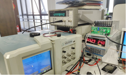
Operating procedure: Connect the crystal oscillator to the frequency counter's REF IN input and connect the GPS PPS signal to the frequency counter's CH1 input. Connect the frequency counter's RS232 serial port to a computer. Allow the devices to warm up upon startup and configure the frequency counter for DC triggering, 2V level triggering, 100KHz filtering, and measurement of the CH1 cycle. With the "Print" option enabled, the measurement results will be received via the serial port. Select the option to save the results in DAT format.
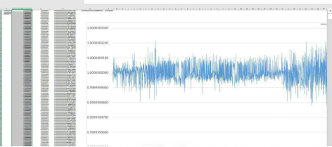
Once a sufficient amount of data is collected, import it into Excel and replace the commas and "s" symbols. Then, use Excel to calculate the average value and create a curve graph. The average value reflects whether the frequency counter's reference source is truly 10MHz, allowing for manual adjustment of the TCXO, OCXO, or rubidium clock's frequency. The curve illustrates the performance of the GPS module, taking into account weather conditions (the right half of the graph represents rainy conditions).
In summary, it is possible to manually adjust the frequency of TCXO, OCXO, or rubidium clocks based on the average value over a certain period, meeting the calibration requirements with satisfactory precision. Alternatively, a microcontroller can be employed to read the frequency counter's data and automatically adjust the frequency. Additionally, with the inclusion of a TDC chip and frequency divider circuitry, microcontrollers can be further utilized.


