DIY HuntKey Power Supply Upgrade Guide


If you have ever modified a decently made HuntKey power supply with a voltage protection range of 7-15V and added current regulation based on available components, but faced difficulties in fine-tuning with regular potentiometers due to voltage fluctuations even with slight adjustments, and found the current regulation inconvenient due to poorly chosen parameters, as well as dealing with buzzing noise, then you can further improve it with the following modifications.
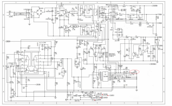
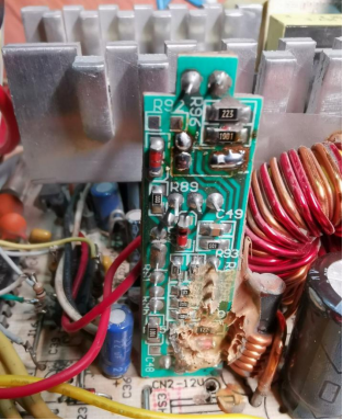
Proposed solution: Replace the voltage regulator with a precision 10k multiturn potentiometer, 30V should be sufficient. Disconnect any irrelevant circuits. Change the current regulation to a 1k (measured 854) 0-10A setup, accurately measure the shunt resistor for the ammeter and calculate the necessary parameters. Add a switch. Introduce an RC circuit to eliminate the buzzing noise. Modify the temperature-controlled fan. Enhance the overvoltage protection. Adjust the short circuit protection sensitivity accordingly.
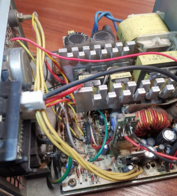
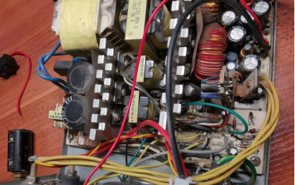
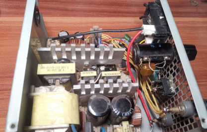
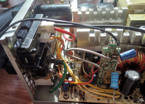
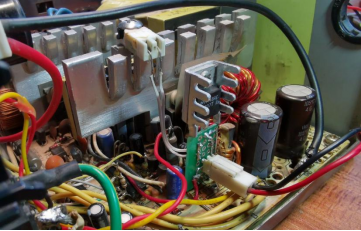
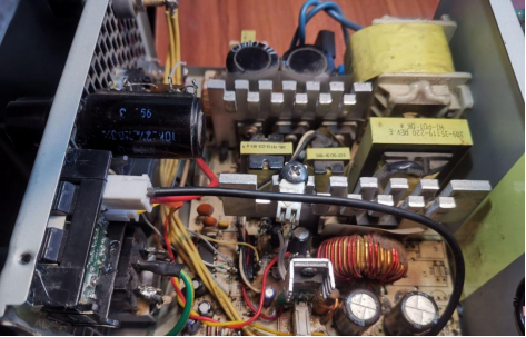
Remove most of the detachable components, leaving only the 12V group intact. Replace the filtering coils at both ends of the original 12V channel with two 35V 470uF capacitors available.
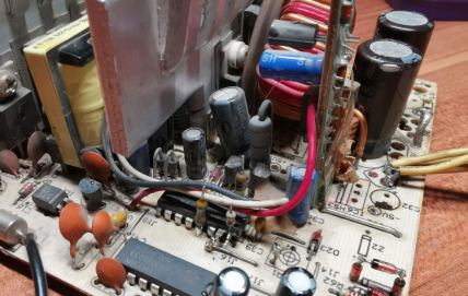
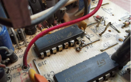
Use pin 15 to stabilize the effect of current regulation and connect it to pin 3 with an RC network to prevent buzzing noise. Sometimes pin 2 may also prove ineffective.
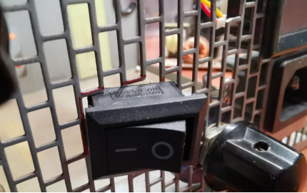
Adding a switch will provide added convenience.
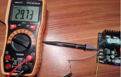
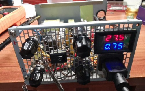
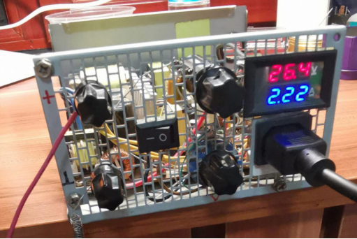
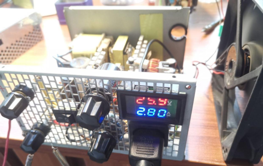
Upon testing, the highest no-load voltage measured was 28V. By adding several voltage stabilizer tubes taken from dismantled devices and connecting them in series with 11.44V, the overvoltage protection can be set to 29.7V.
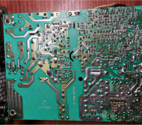
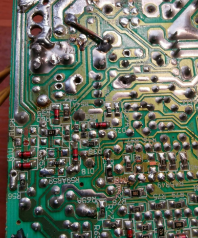
The original short circuit protection was too sensitive and would trigger when connecting an air pump. It can be resolved by replacing the 22-ohm resistor R38 with a 100-ohm resistor.
After connecting various flying wires, connect a 40W light bulb in series to test the device. If the light bulb briefly illuminates and then turns off, check if the voltage adjustment lead is connected to the left end of the 17k resistor. Move it to pin 13 for normal operation. The device is now quiet and free of buzzing noise. The multiturn potentiometer operates smoothly and delicately.
Don't forget to provide a separate power supply for the VA meter. It turned black below 4V, so connect it to the 5VSB.
There is a slight discrepancy between the 47k and 10k resistors, resulting in an unloaded output voltage of approximately 27.9V, which decreases under load.
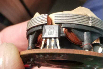
Next, the fan needs to be restored. Upon disassembly, it appears that the Hall driver 276 is the issue. Replace it with another 276 from a spare power supply fan.
The 12V current is only 150mA.
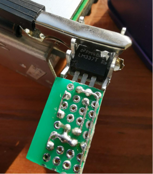
The temperature control solution has become a major problem since the original board uses the 12V and auxiliary 20V, making it more complicated. Alternative approach: Utilize the 20V power supply for the 7500 and use a single transistor with a voltage regulator like 555 and LM317. If an appropriate voltage regulator cannot be found, the 555 with a maximum voltage of 18V could be utilized. If there is a spare 337 transistor, it may also be suitable.
First, attempt to power the 555 circuit directly using the 20V from the 7500. Connect a 120-ohm resistor (the fan equivalent resistance is 75 ohms) to address the transformer's buzzing noise, and add a capacitor.
The 337 circuit appears to be working well with an added R2 of 27k resistor. The fan voltage is close to 6V, which is slightly high, so it can be adjusted to 22k.
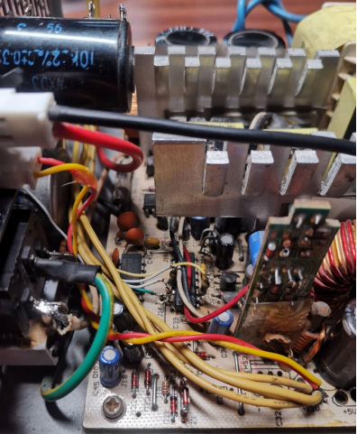
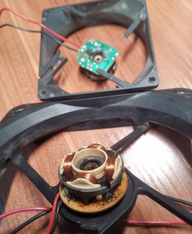
The original board only uses the ground for the 4 pins connecting to the main board. Create a small board to accommodate several components.
Only capacitors are used on the input side, while the fan motor already contains two capacitors, so this shouldn't be an issue, especially considering the low counter electromotive force of the brushless motor.
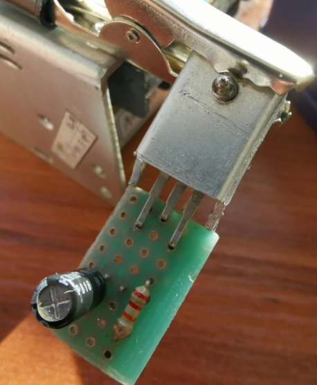
Make slight modifications to the 10k NTC on the discarded power supply. Remove the original adhesive and use AB glue to secure it.
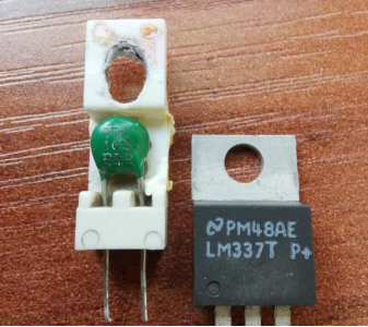
Apply thermal paste to the NTC and fix it as close as possible to the heat sink. Placing it on the primary power dissipation board might yield better results. The 20V can also be connected to the VA meter (4-30V).
After testing, everything appears to be functioning correctly. At 22 degrees, the NTC measures 11k, the fan receives 5.3V, and at 55 degrees, the voltage reaches 12V. One issue is that the fan stops spinning below 3.5V, which is lower than the 276 threshold when it's too cold. There is a risk of the fan burning out when the NTC exceeds 55 degrees, but it shouldn't reach such high temperatures.
Using lithium-based grease for the fan instead of thin oil results in quieter operation and is recommended.
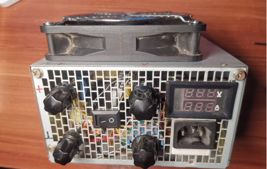
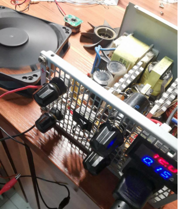
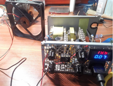
Once completed, the device can be assembled.


