Enhance OZWI Sockets: Power Measurement & Integration


If you have several OZWI standard sockets, you can remove the grounding prongs and use them as two-prong sockets. By dismantling the internals, you can create ample space for modification and power meter addition. With the help of chatGPT, writing the code becomes much easier and efficient.
The proposed solution involves the use of the hlw8012, bl0937, and hlw8032 chips, which are compatible. You can modify three sockets together: two can be flashed with HomeKit firmware for direct integration with Apple Home, and the remaining one can be flashed with ESPhome for integration with Home Assistant.
HomeKit firmware allows you to use the sockets without a central hub as long as you have Wi-Fi. It enables remote control through devices like iPad or iPod. On the other hand, ESPhome requires a central Home Assistant hub, and if the hub goes down, Wi-Fi control becomes unavailable. Installing and configuring ESPhome for remote control can be more complicated, but it offers powerful functionality.
Even without a power meter, you can still flash the sockets and use them as regular smart sockets.
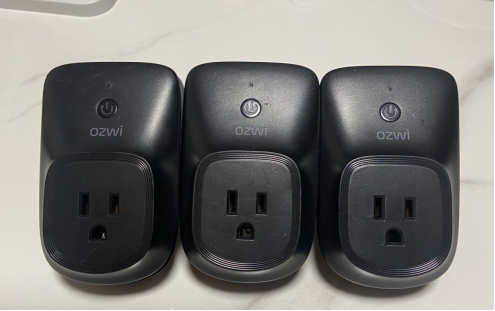
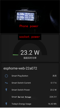
If you don't have a professional power measurement device at hand, you can compare the sockets with finished products and you'll find they are similar enough for household use.
When it comes to connecting fast charging heads, they seem quite accurate, with an efficiency of around 93%.
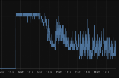
ESPhome can also be integrated with Apple Home through Home Assistant. ESPhome provides a graph that can be used for data statistical analysis.
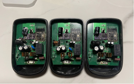
Now let's move on to the modification process.
Many smart sockets on the market use the hlw8012 chip for power measurement. Its drawback is that it is non-isolated, but it is cost-effective. OZWI happens to be a non-isolated power source, but it requires converting from full-wave rectification to half-wave rectification and changing the reference ground (GND) from low voltage to neutral.
It is crucial to follow the steps below for the modification; otherwise, the chip may get damaged.
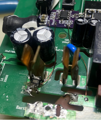
1. Disconnect the front and back positions to make room for the shunt resistor.
2. Disconnect the front and back positions and connect a wire to the neutral line (This step connects GND to the neutral line. If there is interference from the inductor, it can be removed during the operation).
3. Cut the position of the rectifier bridge (This step converts from full-wave to half-wave rectification).
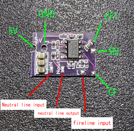
Next, solder the power meter PCB board in place. This board can be used to add a power meter to any socket that uses ESP8266 or ESP32. The wiring method is similar for these sockets.
It is important to note that non-isolated power supplies need to be modified according to the above method. Isolated power supplies only require connecting GND to the neutral line, but the downstream circuit will be live. It is not recommended to make this modification for sockets with built-in USB ports.
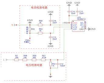
Schematic diagram:
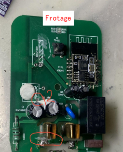
Remove the capacitor and connect the wires and ESP8266 as shown in the diagram.
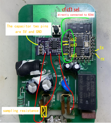
Once everything is connected properly, it should look like the image below.
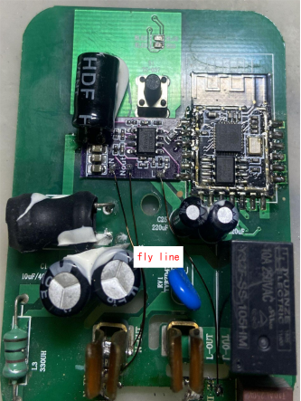
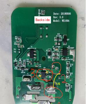
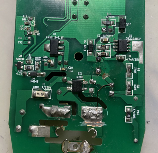
Back view after modification:
Close-up of the shunt resistor position, default value is 1mΩ, but other specifications can be used as well.
Once everything is soldered back in place, it should look like this.
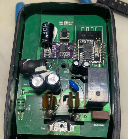
When removing the inductor, be careful not to break the copper wire. If it gets broken, you can still fix it but without closing the case. However, it will still function normally when powered on.
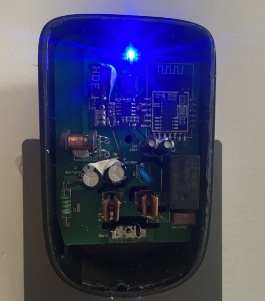
Once you enter the corresponding app, you should see readings. For the initial use, you need to calibrate the power, current, and voltage. App readings = Chip readings x Calibration coefficient. The coefficient can be modified in the respective configuration file. After calibration, it can be used normally. ChatGPT is truly powerful.
If the first one you modify is incorrect, it may cause one hlw8012 chip to explode, and even burn off the copper foil, but the ESP8266 will be fine.

The remaining sockets can be modified following a similar process.


