
Summer is most afraid of power outages, even if it's just for an hour or two, it gets unbearably hot. Setting up a desk fan and finding an extension cord can be quite a hassle.
Ⅰ. Simple Solution
A small fan powered by 18650 batteries has three drawbacks. First, the capacity of the 18650 batteries isn't large enough, so the battery life is limited. Second, the airflow isn't sufficient. Third, the power switch and charging port are located on the back, which is inconvenient. Especially frustrating is the inability to shut it down with a long press – you have to press the button three times to cycle through all the settings before turning it off.
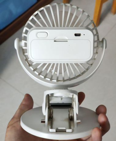
· Detailed Solution
Using this small motor, the brushes are mostly made of thin copper pieces that wear out and break quickly. It's possible to replace the motor with a slightly longer diameter one, adjust the voltage through changes in voltage-dividing resistors to increase power. If the voltage boosting circuit is subpar, consider replacing it with a better voltage boosting inductor and increasing the filtering capacitor. This significantly increases the airflow. Due to the longer motor, the front protective cover can't be put on, and there's a risk of the fan blades hitting your hand when turning on the back switch.
Ⅱ. Elaborate Solution
Take a weighty iron plate as a base, or directly use the kind of phone holder with adjustable angles, use it as a base, and create a lithium battery-powered fan. Having two fans can accommodate multiple users or provide longer usage through relay.
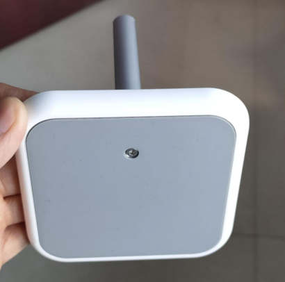
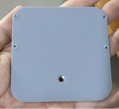
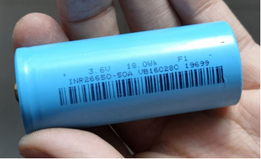
Purchase a 26650 lithium battery with a capacity of 5000mAh for powering the small fan.
Fans can be dismantled from an HP Z420 workstation – older ones are even better, with a side length of 9cm and dual ball bearings. This size is suitable for a small fan.
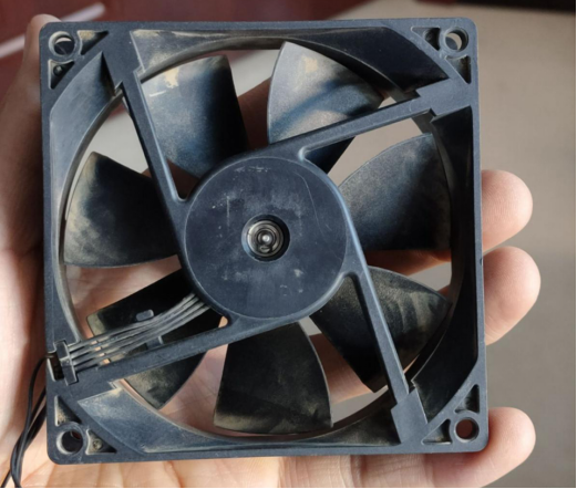
Rated voltage is 12V with speed control wires. After testing, it's only controllable using PWM waveforms; adjusting speed with a potentiometer hardly works. Running the fan at 12V, the lowest speed consumes 0.5W, while the highest consumes 3.8W.
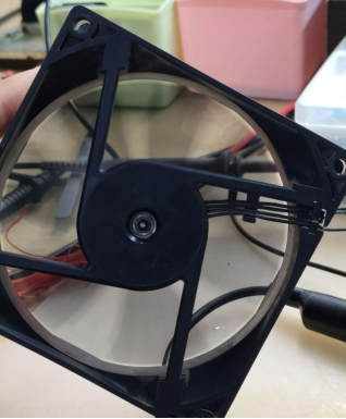
For securing a vertical fan to a horizontal base, directly gluing it might not hold it securely. It's crucial to elevate it to prevent the controller box from obstructing the fan blades. The aluminum pipes from the original phone stand can be utilized. The easiest way to attach a circular pipe to a square fan is to secure one corner of the fan.
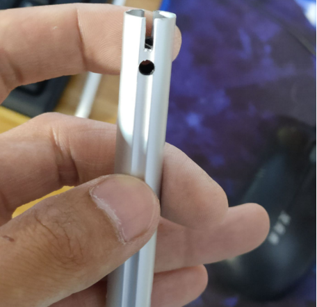
The fan's corners have plastic reinforcement ribs; create notches in the aluminum pipe to fit and secure the fan in place.
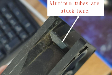
Cut notches in the aluminum pipe with an angle grinder, drill fixing holes with a power drill, insert hard plastic tubing inside to prevent compression from screws. Pass an M4 screw through and tighten with two nuts.
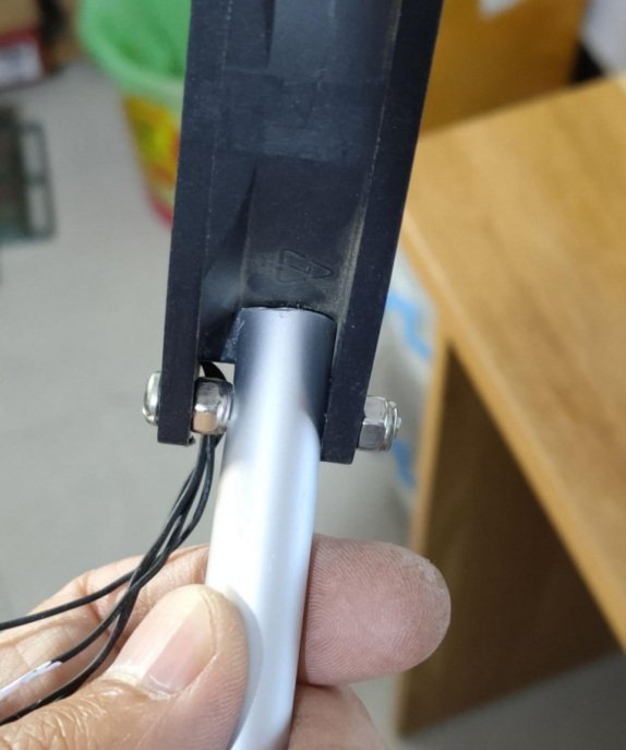
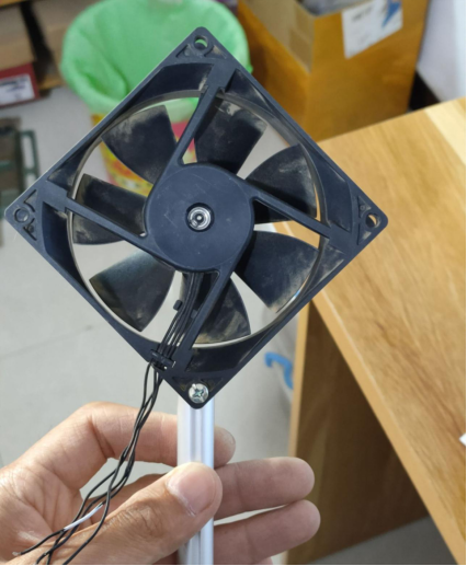
To enhance aesthetics, cables can be hidden within the aluminum pipe. When attaching the aluminum pipe to the base, using thread-locking adhesive ensures stability and prevents unintended rotation.
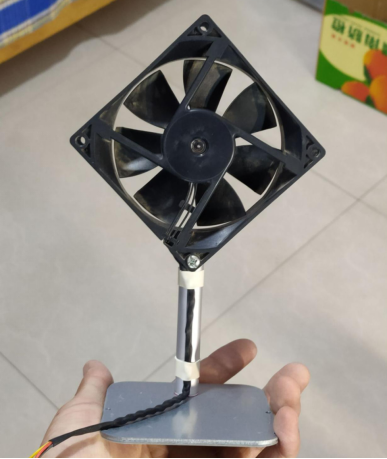
The controller can be housed in a 388838mm aluminum casing, accommodating the 26650 battery and control circuitry.
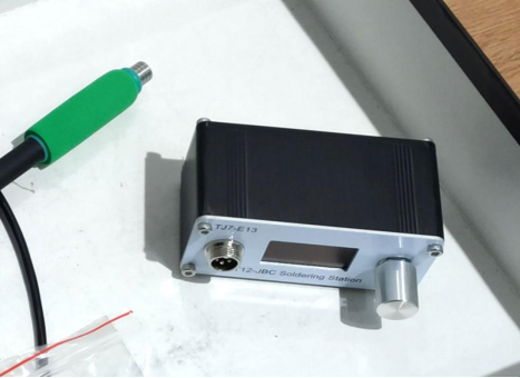
Since the fan doesn't require a screen, an aluminum panel with a screen opening isn't necessary. Instead, process a semi-transparent acrylic panel to fit the current panel.
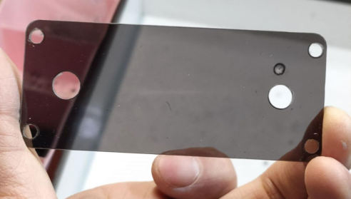
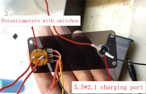
Place a potentiometer with a power switch on the left side, responsible for powering on and adjusting fan speed. On the right side, install a 5.5*2.1mm charging socket. Planning to use a 12V router power adapter for charging.
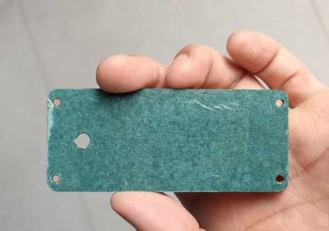
The back panel remains acrylic. The large hole on the left accommodates the fan cables. The back is covered with colored paper to prevent light leakage.
For the modules, use the following: lithium battery protection board, TP4056 charging module, boost module, and 12V to 5V voltage reducer. These provide various functions for powering the fan and charging the battery.
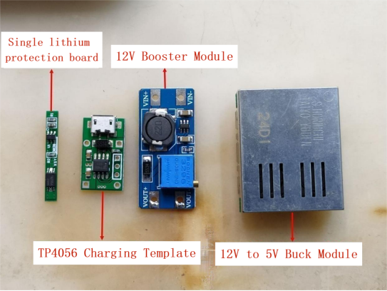
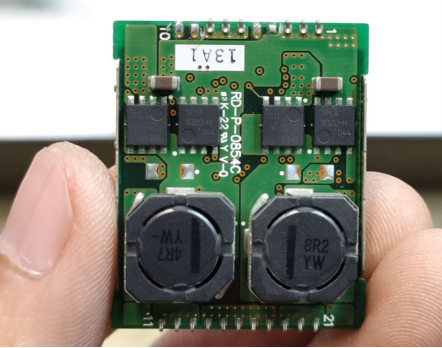
This 12V buck module was originally 12V to 1.8V+3.3V dual, can be changed to 12V to 5V+5V dual. On the top are 4 Toshiba MOS, 2 30V, 2 40V, all are N-channel low internal resistance MOS.
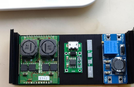
Boost module IC is SOT23-6 package SB6284, especially small, but also built-in MOS, the power will not be large. The switching speed is fast, 1.2MHz. the input peak current is 4A. because this is the peak current, and the current in the MOS is linearly rising, on average, it may only be between 2A and 3A. Considering that the duty cycle can not be 100%, the input average current maybe maximum 2A. Li-ion battery voltage is less than 3V when the power is low, the current is calculated according to 2A, the efficiency is calculated according to 85%, rising to 12V, the input power is maximum 6W, the output power is maximum 5.1W or so.
Module roughly placed, the space is enough. Especially the length of the module, just slightly less than the width of the aluminum case.
Regarding PWM speed control, a simple solution is the versatile NE555 timer IC.
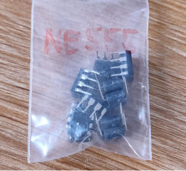
The principle involves comparators, Schmitt triggers, and capacitor charging. The 12V power supply is suitable. A 10K potentiometer is used. The third pin connects to the fan's speed control wire. Building a circuit on a perforated board for testing purposes can help fine-tune the design.
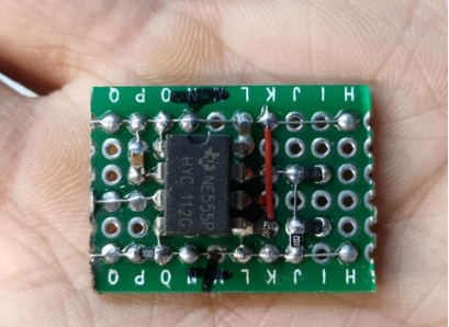
Testing the output waveform, a frequency of around 1.2KHz is suitable. Checking different duty cycles for low and high settings is sufficient.
Note: If the NE555 is connected to 12V in parallel with the fan and the fan is an inductive load controlled with PWM, it can produce significant voltage spikes, potentially damaging the NE555. It's best not to share the power source between the PWM module and the motor.
With all modules ready, place them on the board. Use silicone adhesive to secure the modules to the aluminum casing, aiding in both fixation and heat dissipation. The TP4056 charging module can generate considerable heat due to linear voltage regulation, affecting the charging rate. The boost module also generates substantial heat.
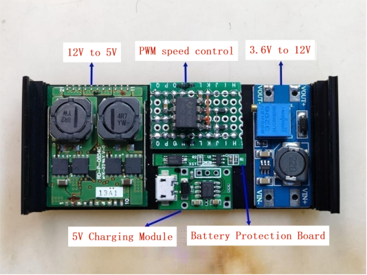
If the power on the fan almost does not turn, 2 MOS in parallel, it will not overload protection.
If the input voltage is lower than 3V, 12V voltage drop a lot, you can use the potentiometer mechanical switch control MOS. The lower the MOS withstand voltage, the lower the gate threshold voltage. You can use TO-252 package MOS. model NCE40H12, N-channel, withstand voltage 40V, on-resistance is only 3.2 milliohms. This is very powerful, the input voltage of 2.8V, the voltage drop is only 57mV, input 4V, the voltage drop is even only 7mV more.
Started wiring. Added 3 indicator lights, one for power on and 2 for charging. Another 12V charging there added Schottky diode, to prevent reverse connection burn module. The lower right corner is the electronic switch made of MOS.
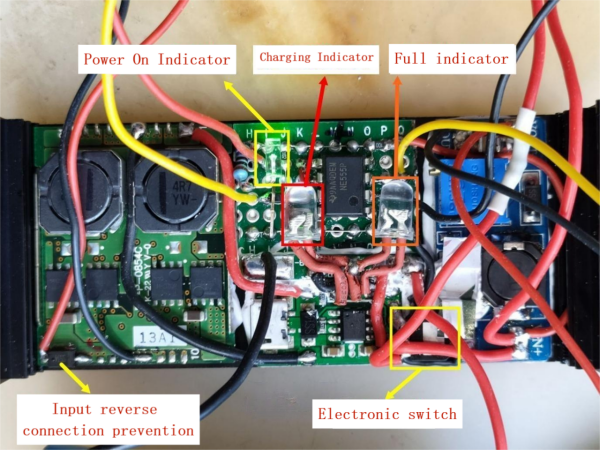
Electronic switch schematic diagram. n-channel MOS, the source level connected to the negative terminal of the battery is considered an input, the drain is the output of the control, connected to the boost module on the line, the MOS gate connected to the pull-down resistor, potentiometer switch connected to the gate and the positive terminal of the battery.
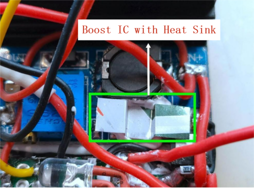
The boost module does reach its limit at the actual maximum speed. The lower the input voltage, the higher the input current to keep the output constant. 3V boost IC is very hot, long time will be high temperature protection cut off the output. SOT23-6 package is too small, it is difficult to dissipate heat. You can use aluminum cans to cut a piece of silicone stick on to help dissipate heat, the effect is good, how long will not protect.
Wiring is completed, including battery connection.
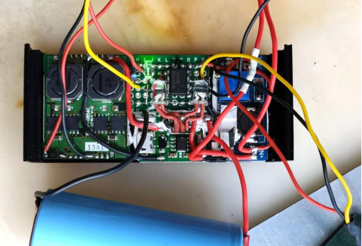
The battery is wrapped in tape for added insulation, with thick double-sided tape on both sides for positive and negative insulation. Attach it with AB glue to the other half of the aluminum casing to prevent short-circuiting with the modules.
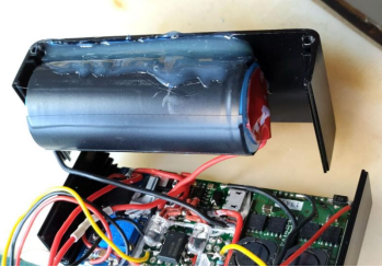
Insert it into the casing, utilizing space effectively.
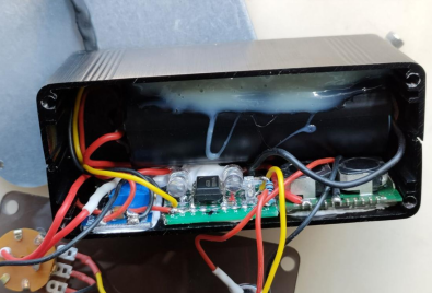
Secure with screws. As it's covered with black paper, it has a black mirror-like appearance.
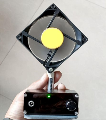
Fully assembled, with a green LED indicating power-on.
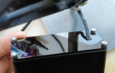
The backside.
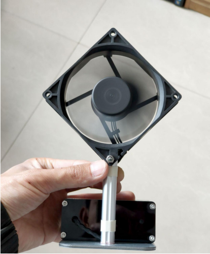
During charging, a red LED lights up.
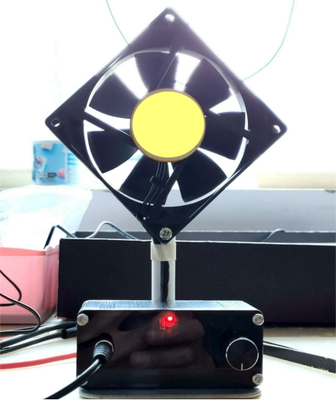
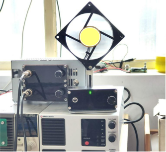
After brief testing, speed control works fine, low-voltage protection works as intended, and it can run at full speed until the battery is depleted without triggering over-temperature protection. The maximum airflow is comparable to the modified brushed motor fan mentioned earlier, and it's definitely more powerful than commercially available single-cell lithium battery fans.
Ⅲ. Summary
Advantages: Portable, smooth variable speed control, brushless motor longevity, high airflow, extended battery life, capable of running at maximum speed for around 2.5 hours.
Disadvantages: Slow charging, 1A charging isn't sufficient for a 5000mAh battery, fixed fan angle, room for aesthetic improvement.
Ⅳ. Possible improvements
1. The electronic switch MOS's gate was initially connected to the battery's positive terminal through a mechanical switch. When the battery's charge is low, the voltage drop is significant (after switching to high-quality MOS), nearly causing the boosting module to function intermittently. Change the gate to connect to the boosting module's output, ensuring that the MOS turns on when the mechanical switch is activated. When the boosting module starts working, the gate voltage immediately becomes 13V, keeping the MOS fully conductive, regardless of the battery voltage. With this setup, the boosting module won't malfunction even when the battery voltage drops to around 2.4V.
2. Another TP4056 charging module is added in parallel, increasing the charging current to 2A for faster charging. Since the current is higher, it can be charged while running at maximum speed. Additionally, this voltage reducing module is versatile, accepting input voltages between 10V and 24V, making it suitable for a variety of power sources. The IC's voltage tolerance is 32V.


