
Discover the art of crafting a highly efficient and user-friendly Automatic Voltage Boost/Buck Module! Delve into the world of cost-effective solutions and cutting-edge technology as we explore the dynamic landscape of voltage regulation. Uncover the prime contenders in the market, from the advanced LT8705 by Linear Technology to the LTC3780EG module. Join us in unraveling the secrets behind a module that strikes the perfect balance between performance and affordability, making waves in both professional and emergency power scenarios.
A cost-effective option for this application is the LTC3780EG automatic voltage boost/buck module. However, the chip cost is high, and it lacks MPPT functionality, which clearly doesn't meet the requirements. On the other hand, the LT8705 from Linear Technology has more available information and is relatively easier to work with.
Product Showcase:
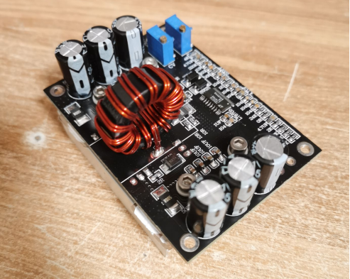
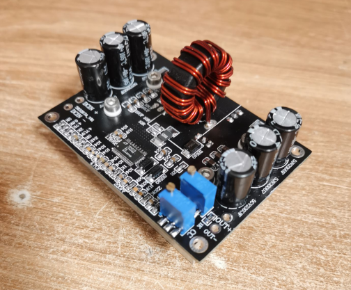
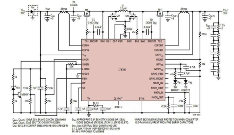
The chip's PDF contains a typical application circuit, and this module is largely based on that circuit with some parameter adjustments.
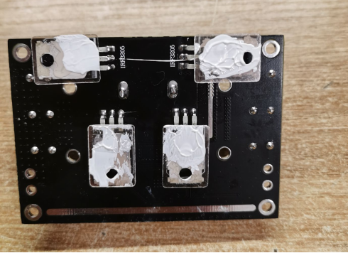
The board utilizes a double-sided design, with the MOSFETs mounted on the reverse side to facilitate heat dissipation, suitable for high-power scenarios. Prototyping and soldering are involved.
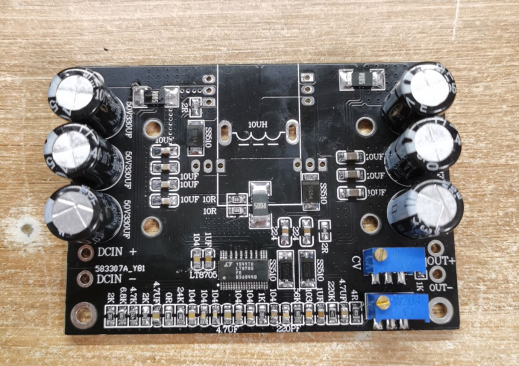
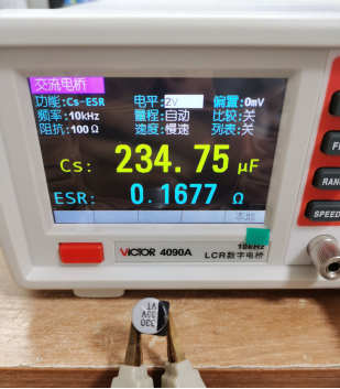
Electrolytic capacitors with low ESR are used to minimize heat generation and improve efficiency.
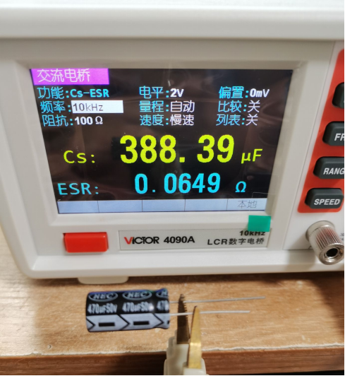
Surface-mount capacitors have higher ESR, resulting in substantial heat generation, especially during high-frequency operations, making them unsuitable for prolonged use.
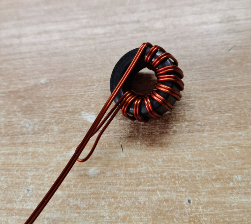
Inductors are manually wound using 1.0 enameled wire in a dual-line bifilar configuration to increase current handling capability.
Two modules are made at once, keeping one as a backup.
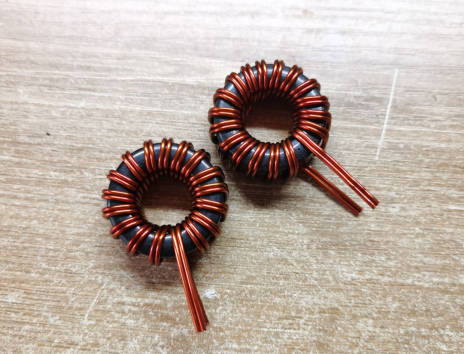
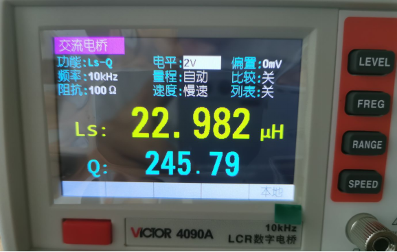
Initial testing revealed the inductance to be slightly high. After removing three turns, the final inductance settled at 22uH with a Q value of 245, indicating good magnetic properties.
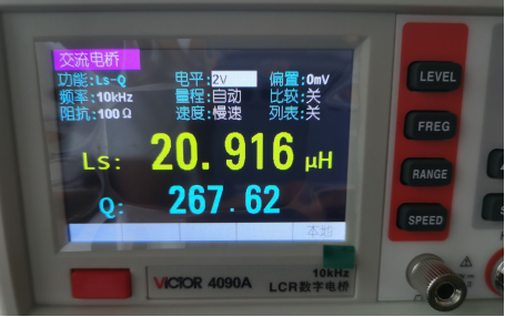
Another inductor has an inductance of 21mH.
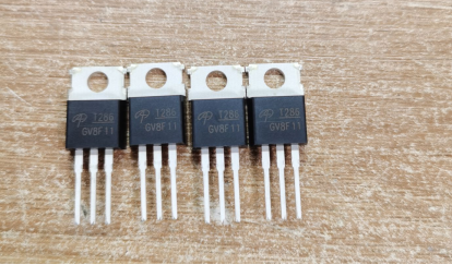
The MOSFET AOT286L is employed. It's recommended to avoid using IRF1010 due to its high reverse transfer capacitance (CRss) and significant internal resistance, which collectively result in an efficiency plateau around 88%.
Mount the MOSFET, apply thermal grease, and place a mica insulator.
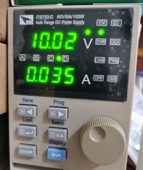
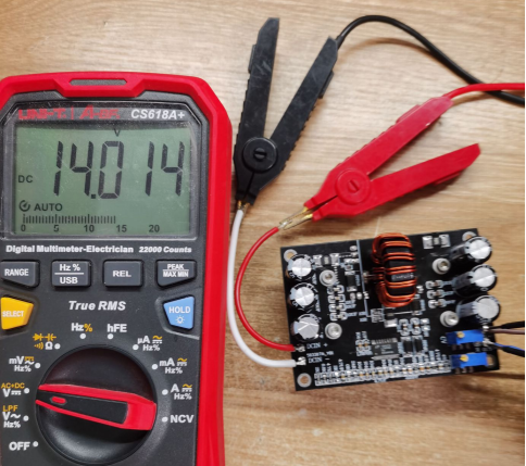
During the power-up test, with an input voltage of 10V and an output set at 14V in forced continuous mode, the no-load current is 35mA.
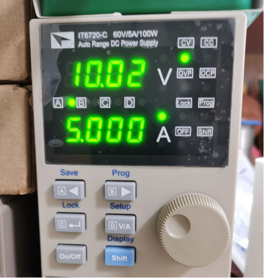
Given the module's maximum output of 5A, the maximum current is used for testing, resulting in an input power of 50W.
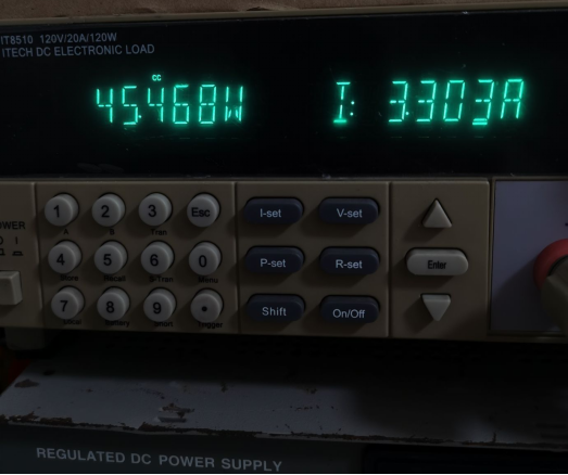
At a load current of 3.3A, due to line losses, the displayed voltage on the electronic load drops to 13.77V. However, the actual module output remains 14V.
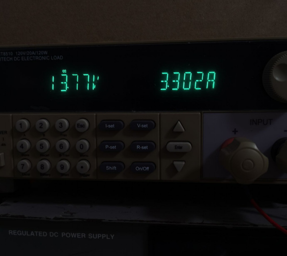
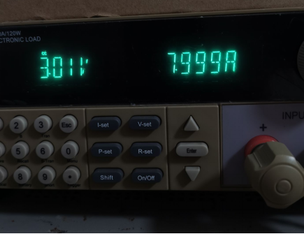
The electronic load indicates a power of 45.468W, but the actual load power is 14V * 3.3A = 46.2W, resulting in a boost efficiency of 46.2/50 * 100% = 92.4% (efficiency would be higher if excluding input line losses).
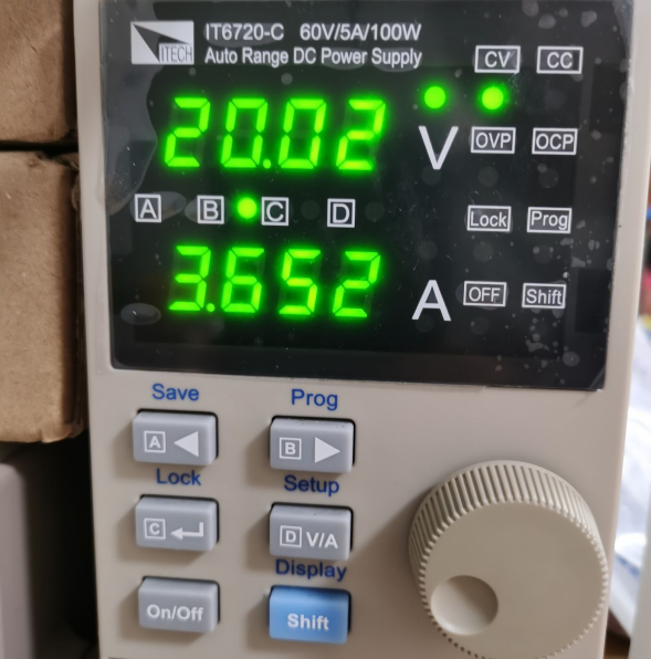
In buck mode, with an input of 20V and a power of 73W.
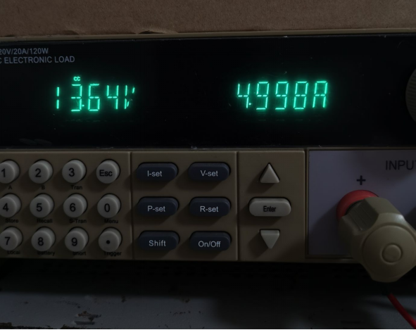
A load current of 5A leads to a displayed voltage of 13.64V on the electronic load due to line losses. Nonetheless, the module's actual output remains 14V.
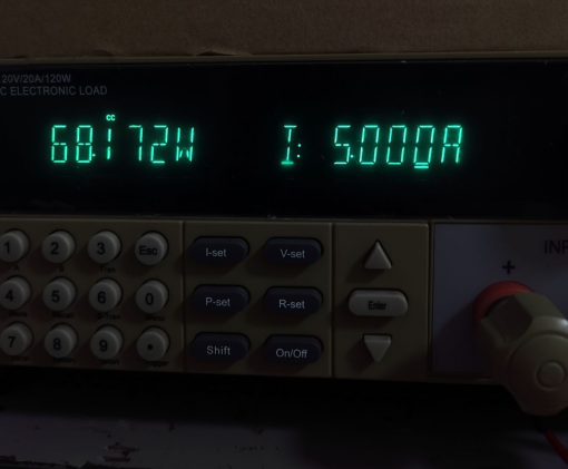
The electronic load displays a power of 68.127W, while the actual load power is 14V * 5A = 70W, resulting in a buck efficiency of approximately 95.9%.
MPPT voltage is fixed at 6.5V; entering a value lower than 6.5V triggers maximum power point tracking. The power source then enters constant current mode, yielding a total input power of 33W.
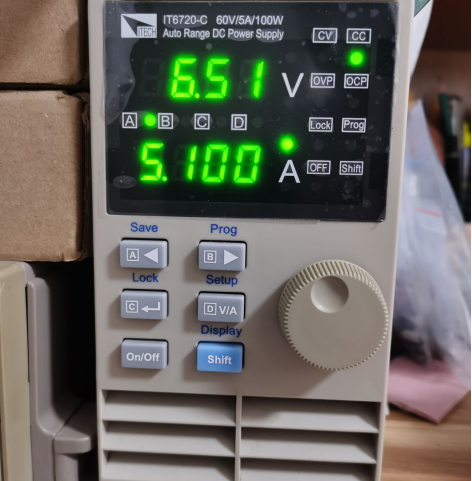
The module adjusts output power proportionally to work at maximum power point during this mode.
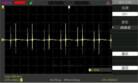
No-load output ripple measures 356mV.
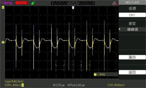
Dynamic testing under high (3A) and low (1A) loads reveals a ripple of 548mV. Given the application for charging supercapacitors, this level of ripple is acceptable.
With these results, the module meets the design requirements, with a temperature increase of only a slight degree (microtemperature) when operating at 3.3A current in boost mode for half an hour. This module could serve as an emergency power source if needed.


