
If you have the source code for the STC microcontroller and the dismantled POS screen, you can attempt to modify the power supply. You can add dual electronic potentiator functionality to the voltage and current meter. This will give you a voltage and current meter with dual electronic potentiator functionality.
First, create the board, then solder it.
You can use an LMV358 rail-to-rail operational amplifier instead of the TP09 operational amplifier. However, ordinary LM358 won't work. Three external keyboard anti-interference filter capacitors are required. If you don't connect an encoder, do not install them, as you won't be able to download the program after installation. Most screens compatible with ST7567 have been tested and found to work. The circuit uses a dismantled POS screen. You can find screens with the model "FM1721625" online. This screen is primarily chosen because of its small size, clear display, and affordability, being a dismantled screen.
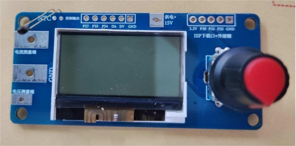
Mingwei Power Supply Modification Special CNC Board 1.0. You can preset voltage and current directly and it has temperature control functionality.
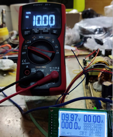
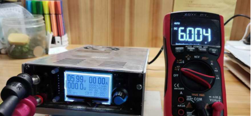
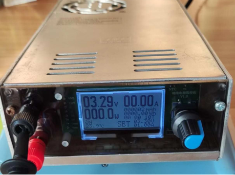
If a relatively complete Mingwei power supply CNC board with electronic positioning functionality is developed, there will be no need to DIY this voltage and current meter anymore.
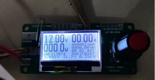
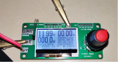
Here is a brief overview of the voltage and current meter with dual electronic potentiator functionality. It's a multifunctional voltage and current meter with electronic potentiator functionality. For modifying adjustable power supplies, it's best to use an encoder for control. You can spend some time redesigning the circuit and writing the program. It's an improved version of the button version, and controlling it with an encoder is very convenient. It displays voltage, current, power, capacity, power-on time, and energy values.
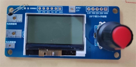
The board dimensions are 72mm x 32mm, very compact and suitable for most power supplies. The screen size is 1.44 inches with a display area of approximately 3.2cm x 1.5cm. The screen model is FM1721625, a dismantled screen from a POS machine. In fact, most serial 12864 screens compatible with ST7567 can be used.
The latest version as of August 24, 2022, allows you to adjust the maximum PWM output voltage in the software. There won't be any more software updates in the future. It has dual electronic potentiators that can be controlled via the encoder to output controllable voltages from 0 to 6.6 volts for replacing those kits that use two precision multi-turn potentiometers and a voltage and current meter head for modifying TL494 chip-based power supplies. The output stage has an added operational amplifier, LM358, for amplification. If you need higher voltage, you can increase the amplification by modifying the resistor values R1 and R8 of the operational amplifier, allowing you to output from 0 to 10 volts. It's adaptable for controlling more power supply modifications.
In the normal interface, a short press of the encoder followed by left or right rotation allows you to adjust the output voltage of the electronic potentiator. It exits the adjustment mode after about 10 seconds of inactivity. A long press of the encoder's center button enters the menu, where you can choose the module to perform functions. After entering a module, you can also exit it by long-pressing the encoder.
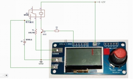
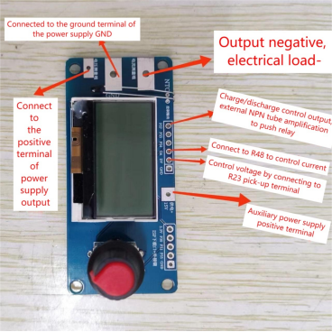
1. It has charge and discharge control functionality. After setting the voltage, current, and timing conditions, pressing "run" will make the P37 control port output a high level. It will stop running and output a low level when the set conditions are met. You can use external relays to control the charging circuit, which can be used to control charging batteries. If not used as a power supply modification kit, this function can also measure the battery discharge capacity. By connecting a dummy load to the battery through this meter and setting the cutoff conditions, you can measure the battery's capacity. The connection for charge and discharge control for capacity measurement is shown in the diagram.
2. System parameter calibration: You can set the encoder direction, temperature protection values, and the maximum output voltage for the two electronic potentiators.
3. Voltage and current calibration interface: After calibration, it will automatically exit.
It is designed specifically for modifying adjustable power supplies like Mingwei power supplies. In theory, it should work with any power supply module that controls voltage and current by adjusting the reference voltage, but it won't work with those that sample the output voltage for regulation. It replaces mechanical dual potentiometers and voltage and current meters, removing some unnecessary functions and keeping only one voltage and current display.
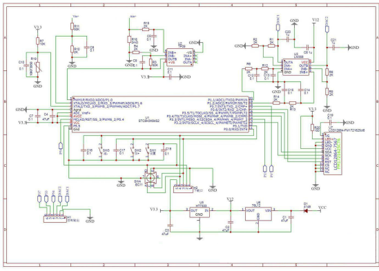
Diagram:
PCB 3D:
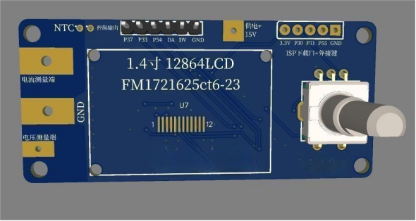
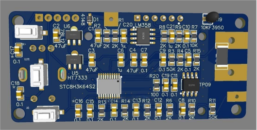
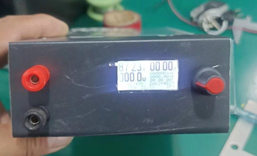
Finished Board:
Running Interface:
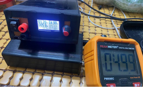
Example of an assembled power supply:
Please note: The original circuit design was not precise. To achieve better PWM filtering, change the resistance values of R6, R12, R14, R13 from 2k to 10k, and the capacitance values of C13 and C14 to 1uF.


