How to Convert an HP 90W Laptop Power Supply into a T12 Power Source?
The HP laptop power adapter, manufactured by Guangbao Technology, is designed with a voltage rating of 19.5V, a current rating of 4.62, and a total power output of 90W. Originally intended for use with a T12 soldering iron, it has been observed to output an actual voltage of 19.76V, enabling the soldering iron to reach a maximum power level of 48.8W (calculated as 19.76 * 19.76 / 8). However, it tends to struggle with larger solder joints. To address this issue, a potential solution involves disassembling the power supply and making some modifications.
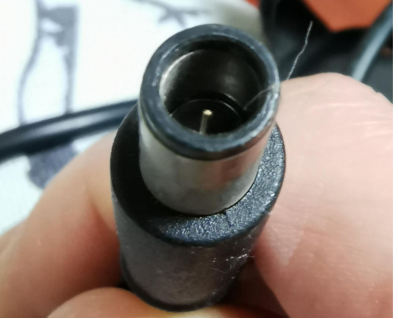
The output plug's structure:
Tools required for disassembly:
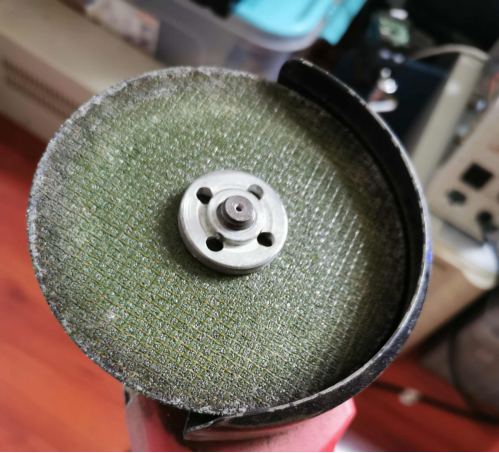
Proceed with disassembly cautiously, avoiding accidental wire damage:
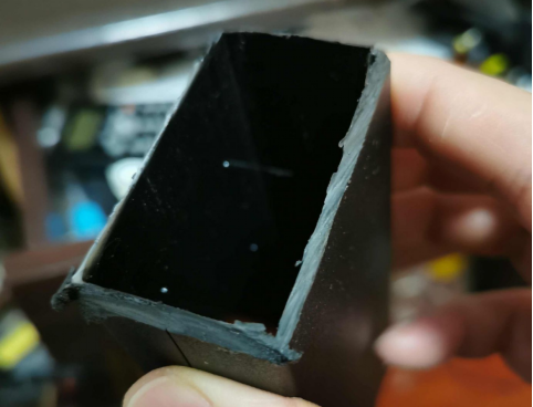
Carefully peel off the shielding cover:

For voltage regulation, the power supply employs a MOSFET-based synchronous rectification system to minimize heat generation and enhance overall efficiency. The MOSFET control chip features 8 pins, although the precise model remains unclear.
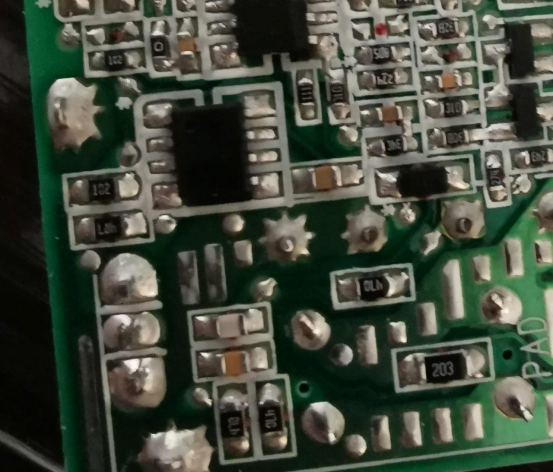
Another 8-pin chip, which has undergone some sanding, is used for voltage stabilization:
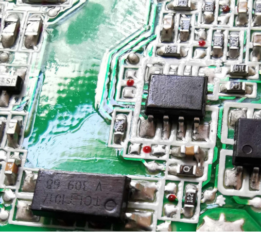
Upon circuit analysis, this chip appears to be a PA4310. It operates with pin 2 for voltage regulation sampling, bearing similarities to a TL431. It is paired with a 34C resistor (22.1K) in parallel with 50B (3.24K) and 274 (270K) resistors. The overall parallel resistance is 3.2K, yielding an output voltage of (22.1/3.2 + 1) * 2.5 = 19.76V.
To implement the modification, the plan involves removing the surface-mount device (SMD) resistor 274, attaching two wires to its pins, and connecting a precision potentiometer. An output voltage of 24V is achieved when the potentiometer resistance reaches 12.43K.
Important Note: Ensure you replace the two filter capacitors:
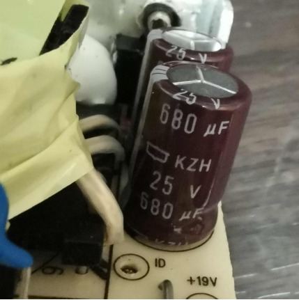
A circuit analysis reveals the purpose of the center pin on the HP output plug. The PA4310 generates a 2.5V reference voltage, which is divided to 20mV on pin 6. Pin 5 utilizes a current-sensing resistor, R211, believed to be an alloy resistor wire with milliohm-level resistance.
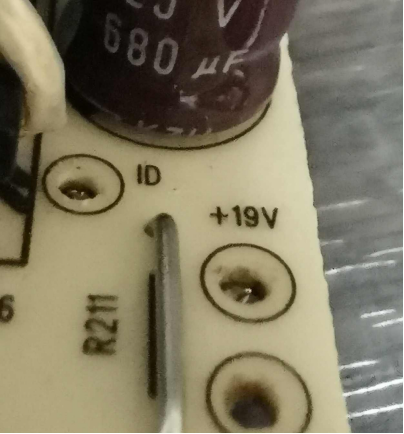
The detection voltage is critical. When it exceeds 20mV, pin 7 outputs a high signal. Two transistors turn on, altering the center pin's pull-up resistor (in parallel with 274 and 203) from 294K to 30B. Under conditions of grounded resistance, the center pin voltage increases, indicating an overcurrent situation, essentially serving as a signaling mechanism.
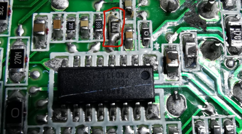
To carry out the modification, remove SMD resistor 274 and connect two wires to it for an external precision adjustable resistor. In practice, this transforms the power supply into an adjustable power source solution. Should adjustability be unnecessary, the onboard adjustable resistor suffices, as illustrated below:
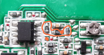
Remove the three SMD resistors along the red line, and short the two red points in the diagram to utilize the onboard adjustable resistor for voltage adjustment. This expands the voltage adjustment range to approximately 21V to 46V.
Upon comparing pin connections, it is tentatively concluded that the voltage regulator chip could be an AP4310 or TSM103AI. The synchronous rectification control IC likely resembles LTA806N, delivering functions akin to TEA1791. The power control IC corresponds to LTA803N, similar in function to TEA1751.
The overvoltage protection feature on this power supply resides on pin 4 of the main control IC. It gauges voltage at a millivolt level with slight fluctuations. When adjusting the output voltage, the voltage on pin 4 progressively increases. Upon surpassing 33mV, the power supply protection initiates, necessitating a power cycle to reset. Pin 4 connects to the transformer feedback winding via a resistor. It remains uncertain whether augmenting the resistance value can elevate the overvoltage protection threshold and whether any undesired consequences may ensue.
Pin 4 interfaces with the feedback winding, and theoretically, higher resistance values lead to reduced feedback. Replacing SMD resistor 88C with SMD 474 substantially increases the resistance value. Under power, voltage can be gradually increased. Attempts to adjust it to 28V were made, with some adjustment range left on the potentiometer. Yet venturing higher seemed inadvisable. Returning the voltage to 24V effectively completes the modification. The ultimate test now lies in its performance stability under actual usage conditions.
