Continuing from our previous discussion on Upgrade Your Honda CRV Audio System for Home Use with Ease! along with Enhance Honda CRV Audio: DIY Casing & Upgrade, we've achieved commendable results in enhancing the system's functionality.
However, certain issues need addressing. Following a power outage, the system fails to automatically rescan radio stations, and it doesn't resume playback from the previous state; instead, it defaults to the lowest volume setting. A straightforward solution to rectify these concerns involves the addition of a lithium battery to the 5V terminal of the power chip (pin 13 of LV5694P, across capacitor C1112). A 3.3V lithium battery is suitable for preserving memory, drawing approximately 2mA of current. To ensure proper charging and protection, it's advisable to use a 12V to 5V converter along with a TP4056 charger. This approach is particularly beneficial when your lithium battery lacks a built-in protection circuit.
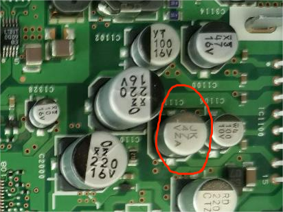
Upon integrating the memory feature, the audio system will seamlessly resume playback at the previous volume setting when powered on with a 12V supply, eliminating the need for manual volume adjustments and power toggles.
The original power button need not be rendered obsolete. It can be repurposed effectively by connecting it to a bistable switch that directly controls a relay, managing the 220V power supply.
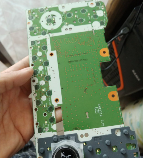
This transition necessitates disassembling the dashboard circuit board, removing the volume control encoder, and identifying the power button. Subsequently, the grounding connection of the power button should be severed, and a dedicated wire routed for it.
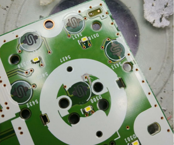
It's important to note that as the board features grounding on both sides, these connections need to be cut on both ends.
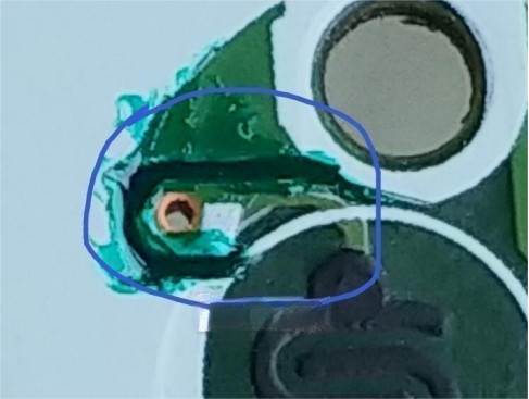
If you have access to green solder mask, applying it enhances durability.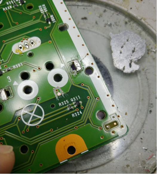
After configuring the panel's PCB connections, the components can be reassembled.
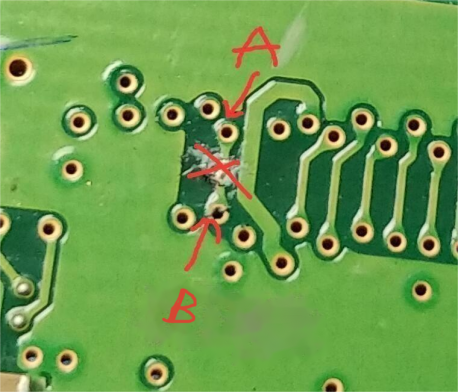
To further streamline the process, on the mainboard, a specific line needs to be severed.
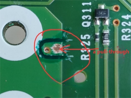
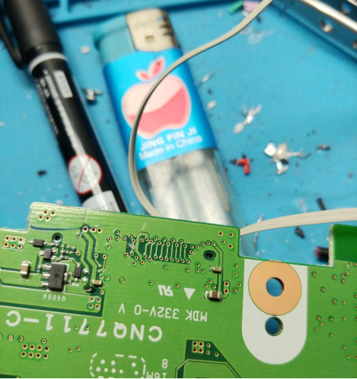
After this incision, two wires must be connected: one designated as A, and the other stemming from the panel, controlling the relay. Grounding wire B can be repurposed for the original power button, and an additional button can be incorporated into the back panel. The relay's switch can serve as a failsafe power switch in case the memory battery depletes and prevents the system from powering on.
A schematic for the bistable switch is provided.
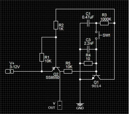
It employs a 5V relay, although it has been tested to function reliably at 2.9V. Key components include a 10K resistor (R4), with the option to substitute an 8550 transistor with a 9012 if needed. Additionally, the 2.2nF capacitor can be swapped with a 0.22uF capacitor. The relay coil should be connected directly to the out terminal, protected by a diode across the coil terminals.
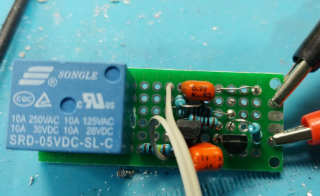
Upon implementing these modifications, the system will exhibit enhanced performance.
Moving forward, let's discuss some straightforward adjustments for the audio system.
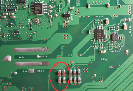
If you find the bass response lacking, consider shorting one of the two series input capacitors. If you have access to higher-quality input capacitors, replacing these components may result in improved bass performance. Be mindful that shorting the capacitors can lead to increased heat generation in the amplifier chip. Adequate heat dissipation measures should be taken to address potential overheating issues.
