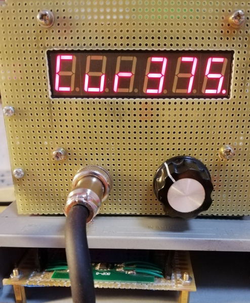
In this project, the STM32F103ZET6 from the 103 series was selected, featuring an LQFP144 package, 512KB FLASH, and 64KB SRAM. Employing one ADC channel and two timers during the process.
The compilation environment is the common MDK 4.74, with JLINK for emulation and debugging.
The overall architecture comprises F103, a 6-digit 8-segment LED display, LM358, rotary encoder, and a 8KB ferroelectric storage MB85RS64.
The software flow begins with powering on, reading the temperature set by ferroelectric storage, then obtaining the ADC value of the soldering iron tip. Based on the comparison and difference in values, it determines whether to enter the heating or temperature measurement process, adjusting the duty cycle to change the heating time slice. This ensures a longer heating time when the temperature difference is significant initially and shorter as it approaches the set temperature, with a fixed duration for temperature measurement.
The advantage of adjusting the duty cycle is faster initial heating, avoiding slow heating or overshooting. The physical heating speed depends largely on the power supply; T12 is recommended to have a power supply of 24V, 2A or above.
The display begins with "On," followed by a jumping animation of OoOoOo and oOoOoO. After reading ferroelectric storage, it displays the temperature of channel 1 as "1SC" and then the current temperature as "Curxxx." Pressing the encoder button shows "SETxxx," allowing temperature adjustment with left or right rotation. Pressing again saves the temperature to ferroelectric storage.
Using common anode LED displays, driving with PNP 8550*6, dynamic scanning with TIMER2 overflow every 2ms, key recognition with TIMER3 overflow every 1ms, a 10ms state machine, and ADC using a polling method. Analog SPI is used for reading/writing to the ferroelectric storage. Power is supplied by Lenovo's 19V, 4.74A laptop charger.
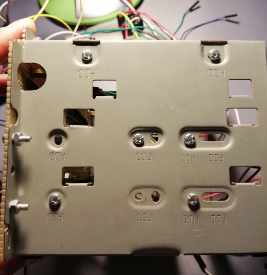
The casing can be made from materials such as hardware floppy disk casings.
Hardware includes a floppy disk casing,
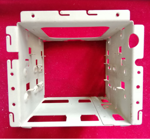
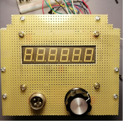
hole-filled panel,
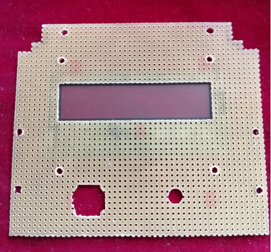
fitting LED displays, aviation socket, rotary encoder,
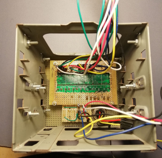
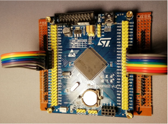
78L05 + PMOS ME4435 + LM358,
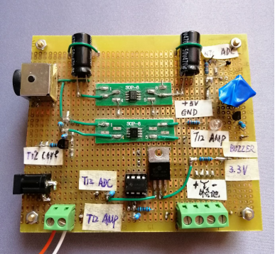
ferroelectric storage,
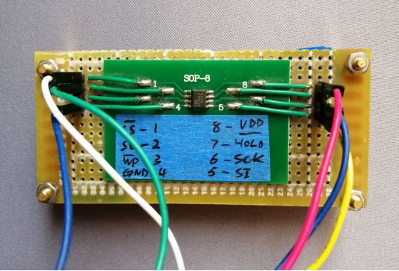
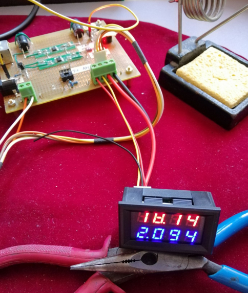
and a power supply.
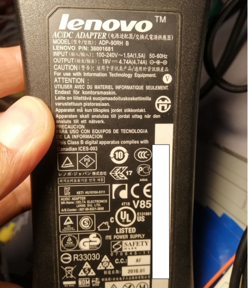
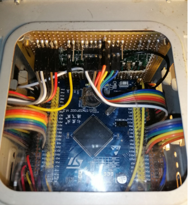
Assembly involves placing the main control board and LED driver board into the floppy disk casing, utilizing acrylic for a perfect fit.
Two optical drive boxes house the LM358 board + ferroelectric board and the power switch with a boat-shaped design.
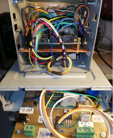
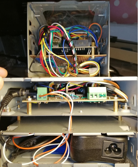
Existing screw holes are maximally utilized, with only two additional holes for connecting the floppy drive and optical drive.
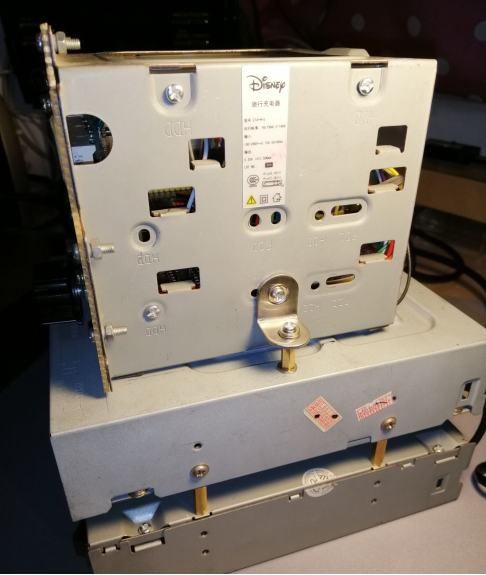
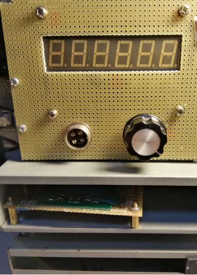
A regular soldering iron is modified by removing the heating core and tip, enlarging the structure, and fitting a T12 horseshoe tip.
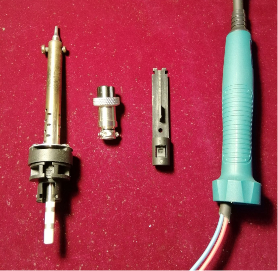
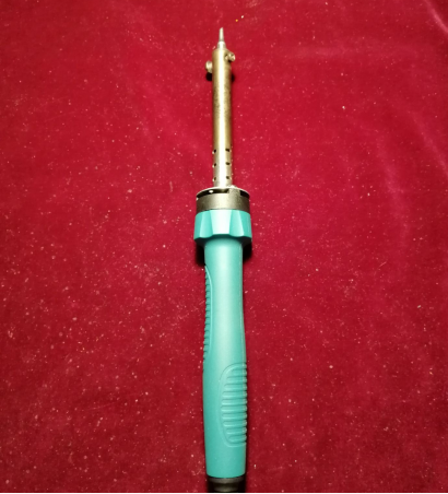
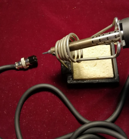
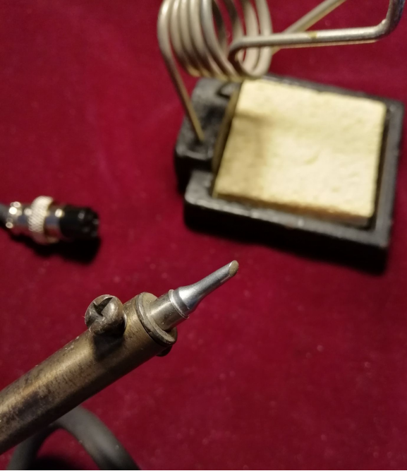
In use, other components like displays and MOS transistors can be improvised based on available materials.
