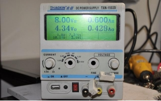
We are pleased to showcase the upgraded M8V7 power supply, now featuring a prominently enhanced display with larger fonts. This modification not only improves visibility but also introduces additional functionality, with the display dedicated to showcasing voltage and current output for both 5V and 12V. Below is a detailed account of the meticulous process undertaken for this modification.
Modification Process:
1. Successful completion of the M8-LCD2004 interface adaptation.
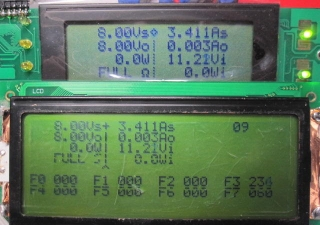
2. Seamless transfer of the adaptation to the 3290 board, specifically designed for Koala's power instrument panel. The original LCD display, deemed too faint, has been repurposed for additional voltage measurements.

3. Achievement of a refined layout for the large font display, demonstrating comparable refresh rates to the M8-LCD2004. Notably, the 3290 crystal oscillator is set to a robust 16M.
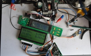
4. Introduction of a cursor and separator line, meticulously ensuring that the cursor's blink aligns seamlessly with the original design.

5. Implementation of a dedicated cursor for precise voltage adjustments.
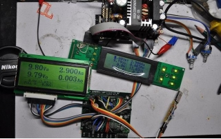
6. Successful amalgamation of the 3290 and 19264, with the replacement of DuPont wires by direct soldering using high-quality wires.
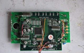
7. A comprehensive display of the modified front view.
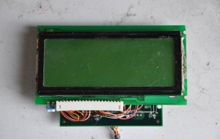
8. Detailed illustration of the bottom view, showcasing the intricate modifications.
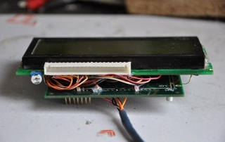
9. Trial installation onto the panel, necessitating the careful trimming of both sides of the 19264, resulting in the adjustment of 13 wires.
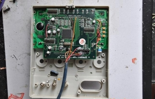
10. A captivating group photo featuring the integrated panel and power supply board. A call to action is presented for a wider iron frame to avoid excessive trimming, with the suggestion of using a thin sheet for added protection.
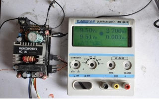
11. A visually appealing presentation of the completed assembly from the top view, highlighting the innovative approach of drilling three holes on the large heat sink for secure threading.
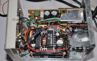
12. A professional depiction of the right view, showcasing a strategic solution to the height of the 1000u capacitor on the control board through the use of two copper pillars.
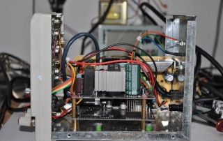
13. The left view, presenting a refined adjustment to the 2N3055 transistor from the original power supply.
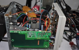
14. A comprehensive display of the rear view, ensuring a holistic view of the modifications.

15. A succinct overview of the constant voltage mode, emphasizing the switch to USB and 12V output, strategically placed in the middle for user convenience.
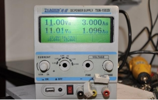
16. A brief description of the constant current mode, highlighting the flexibility for future adjustments in the post-assembly phase.
