
Discover how to assemble a customized power supply with the following components: a 36V 5A switch power supply board, XL4015 5A DC-DC buck module, or XL4016 8A module, and a voltage digital display.

Follow these step-by-step instructions for a seamless build:
Material Selection:
Begin with a quality medium-density board for the foundation of your power supply.

Board Preparation:
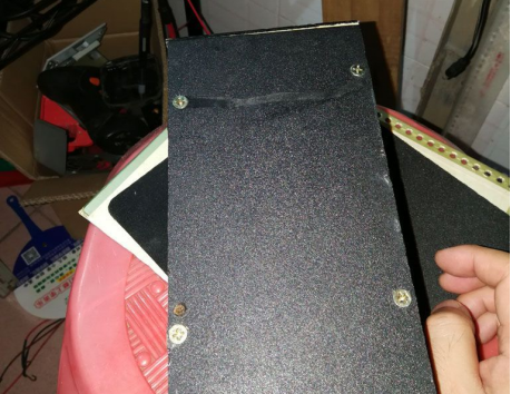
Precision is key - cut, screw, and glue the board meticulously for a sturdy foundation.


Heat Dissipation:
Drill strategically placed holes to ensure effective heat dissipation for optimal performance.

Mounting:
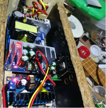
Carefully position and secure the components to achieve an optimal layout for functionality.

Panel Design:
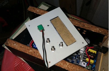
Craft a durable ABS panel with a tea-colored glass window for the voltage digital display.

Circuit Integration:
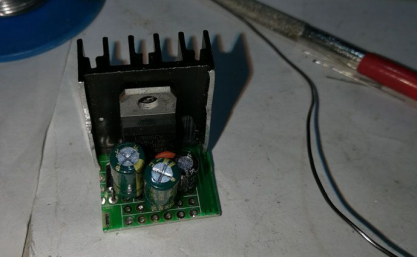
Ensure low voltage accuracy by soldering a 7805 inside the circuit.
Digital Display Optimization:
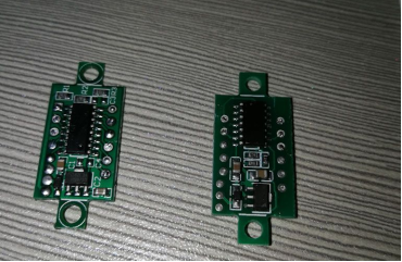
Repurpose the digital tube from the original display or DIY a new one for enhanced measurement and display capabilities.

Programming:
Fine-tune the program settings, download, and thoroughly test for seamless functionality.

Pre-Installation Prep:
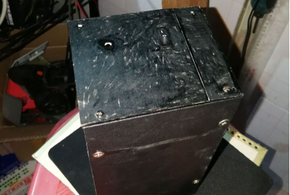
Before installation, mark the bare board positions for a polished finish.
Foot Pad Application:
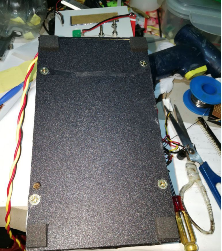
Enhance stability and aesthetics by attaching two foot pads to the assembled power supply.
Final Product:
Admire the finished product - a professionally crafted power supply unit.

Power-On Experience:
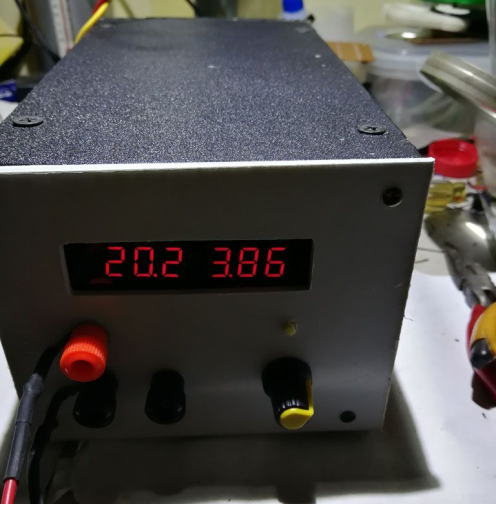
Power on, the left side is the voltage meter, the right side is the current meter, below are the ON/OFF and voltage knobs, the current part displays "---" indicating OFF.

MCU Consideration:
If you use an MCU for everything, the PWM speed and accuracy may not be sufficient, and driving the MOS tube at high speed is a problem. If you want to control the DC-DC for CNC, using a single MCU system seems unreliable. Therefore, it's only suitable for measurement.
Overcurrent Protection:
Implementing overcurrent protection is completed. The image below shows setting the protection current to 4000mA, long press ON/OFF to enter the setting screen.

Load Testing:
Add a load, 20.2V, 3.86A, minimum accuracy 1mA. When the current is less than 1A, it displays in mA, up to 999mA. When it reaches 1A or more, it displays x.xxA.
Conclusion:
The electronic load shows 3.88A, with a slight error, but it's generally usable.

Your DIY power supply is now ready for various applications.


