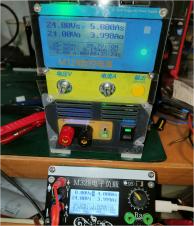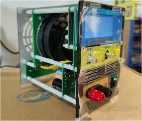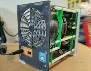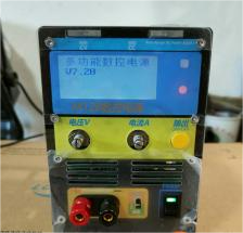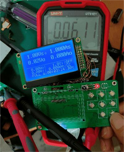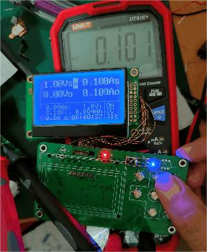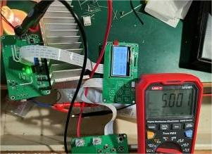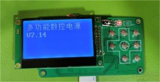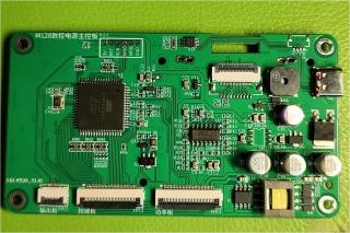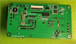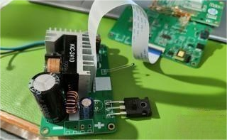
The power supply design of this project is based on a 20V 5A configuration. If you need different voltage and current values, please modify the principle parameters on your own. Detailed instructions, including specific locations and explanations, have been thoughtfully annotated for your convenience.
1. Performance and Debugging:
Following meticulous debugging, the power supply exhibits no discernible issues. Notably, the most significant enhancement over previous iterations lies in the alteration of the tracking method, ensuring the power supply maintains zero idle current.
2. Physical Dimensions:
Structure Size: 100130150mm (Width Height Length, adjustable down to 130mm)
Power Input: External DC input
Compatibility and Display Options:
3. Upper Computer Support:
Compatible with DPS series software from a reputable brand.
Main Control Board Integration:
Three LCD displays - ST7567 Monochrome LCD, 12864-469 COG LCD, and 12864b11.
4. Independent Display Board Recommendation:
Utilizing a 2.8-inch screen with a favorable screen ratio, the option to modify the board independently is provided. Alternatively, a separate display board, featuring compatibility with CC, CV display lights, on/off LED, and infrared reception, can be created.
5. Transformering Wind:
All windings use 0.15mm enameled wire. Wind according to personal preference, either clockwise or counterclockwise for the primary winding.
· Primary winding: 22 turns, dual wire, wound in two layers. The actual circuit is two windings in parallel, but a single winding is also acceptable.
· Secondary winding: 15 turns, dual wire, pay attention to matching terminals. Default voltage is determined by input voltage and turns, so calculate carefully. Adjustments are needed for other voltages.
6. Heatsink Selection:
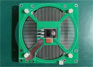
Since the voltage segments are fine, the maximum voltage difference is about 2.8V, which is the adjustment on the highest voltage on the transistor. With a 10A current output, the maximum heating of the adjustment transistor is around 30W. Therefore, the heatsink does not need to be very large. Of course, larger is better if space allows.
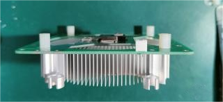
Using an AM4 heatsink for Ryzen. It has sufficient heat capacity, is inexpensive, and can be bought for less than 10 dollars, including a fan. Tested with a 15W heat load and didn't reach 40°C in half a day. This structure seems suitable for the load.
7. Fan Driver:
High-speed optocouplers are recommended for the fan driver for a simple circuit without additional power consumption (recommended). Regular low-speed optocouplers require an additional circuit to increase static current by 20mA.
8. DCDC Module Modification:
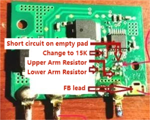
According to the Excel table at the end of the document, modify the module to output a fixed minimum voltage, such as 2V. Connect the FB directly to the interface to the main board.
9. DCDC Module Replacement with KIC0210:
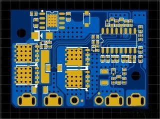
The default scheme is for a 2V 10A output, suitable for M128 adjustable power supply. Replacing the original KIC scheme TPS40057 may cause whistling due to possibly low frequency. Use with caution.
10. Additional Information:
M328V7 New Features List:
· Supports Atmega328P/Atmega644P/Atmega128/Atmega64
· Supports 12864 (LCD/OLED) with both Chinese and English interfaces
· Displays voltage and current curves
· Built-in universal smart charger mode
· Built-in signal generator
· Built-in universal infrared decoder
· Supports default output voltage on power-up/default shutdown output/use last shutdown state
· New features include runtime display, scheduled power on/off, and periodic power on/off
· Supports no-load current deduction
· Multi-point calibration for better accuracy
· Maximum power protection, short circuit protection, temperature protection, automatic fan control
· Separate ON/OFF button
· Supports 8 sets of preset voltage and current
· Serial control, compatible with a certain brand's CNC power supply upper computer
· Supports control of front-stage voltage following or winding switching
· Various other improvements
