Many individuals have invested in LED large screen clocks, commonly referred to as perpetual calendars. These clocks boast expansive screens, cost-effectiveness, and, in comparison to LCD counterparts, emit light spontaneously, ensuring clear visibility during nighttime hours. They offer user-friendly operation, significantly surpassing the convenience of checking time on mobile devices. Positioned at eye level when wall-mounted, these clocks provide an easily accessible time display, presenting numerous advantages that contribute to a substantial market presence.
While these clocks offer a myriad of features, the paramount functionality of a clock as a household essential lies in its readability and clarity. Let's explore the process of creating a customized clock that addresses this critical requirement.
However, a notable drawback of existing clocks is their imprecise timekeeping; the crystal oscillator falls short in comparison to Japanese clock counterparts. With a daily deviation typically ranging between plus and minus 1-2 seconds, these discrepancies accumulate over months, resulting in a deviation of several minutes.
Moreover, the inconvenience of adjusting wall-mounted clocks at a height makes achieving automatic and precise time calibration a challenge for many electronics enthusiasts.
Post-2010, LED clocks have incorporated chips supporting instrument calibration. PCBs often include a 3-pin calibration socket, allowing for automatic precision time setting during factory production. Equipped with a 3V lithium battery for time retention, LED clocks delivered to end-users ensure accurate timekeeping.
Achieving accurate time involves four potential sources: GPS signals, CDMA signals, 68.5K radio wave clock signals, and NTP servers on the network.
1. GPS signals require proximity to a window for reception and are impractical indoors. Additionally, high power consumption and cost make them viable only in outdoor, network signal-absent scenarios.
2. CDMA signals necessitate a telecommunications CDMA base station and a mobile phone card, with a high implementation cost and complexity. With CDMA on a phasing-out trajectory, it's not a viable long-term solution.
3. The 68.5K radio wave clock signal, once a promising solution, faces challenges in complex electromagnetic environments and is challenging to receive indoors. The signal reception also depends on weather conditions.
4. Network clock signals emerge as the most reliable solution. With widespread broadband availability and WiFi signals ubiquitously present, utilizing an IoT WiFi module connected to network NTP servers offers a robust solution. This ensures perpetual accuracy for household LED clocks, provided that error accumulation remains minimal.
Regarding radio wave clocks, there are several issues that make these products almost unsuccessful.
LED clocks are powered by AC, while other radio wave clocks and radio-controlled watches are powered by batteries. The AC power module interferes severely with the 68.5K module within a one-meter range. Although this module is inexpensive, the signal is very weak and cannot be measured with an oscilloscope due to interference; a lithium battery-powered oscilloscope must be used, and it must not be close to computers and all household appliances, making the usage conditions demanding. Embedding it into an LED clock is almost impossible.
If using a master-slave clock configuration, where the radio wave clock receiving module is a separate battery-powered master unit using a low-power microcontroller for decoding, and sending the decoded signal via a 2.4G module to the LED clock receiver, there are challenges. While the prototype works well in the lab, it is practically unusable for users. The reception conditions are demanding, and finding a stable signal point in densely populated urban homes is difficult. Moreover, the master unit runs out of power after a few months and requires frequent recharging, even with the addition of a solar panel. Exposed to wind and rain, the master unit becomes dysfunctional after a while.
Therefore, it is advisable to use radio wave LED clocks only in watches in China—battery-powered, fully enclosed, and portable.
Additionally, the encoding scheme for Chinese radio wave clocks is relatively simple and immature compared to Japan. Japan transmits every 60 seconds, while China transmits every 20 seconds. The signal is not clear enough, and the 0s and 1s are not distinct. Decoding in base-4 is difficult, and the checksum design is irrational. There is only one checksum bit, and the checksums for 01 and 10 are the same. This results in a time difference of 20 seconds. The original clocks often receive data with a 20-second difference. A two-bit checksum would have been more reasonable. The redundancy inside the signal is extensive, making subsequent programming challenging. Decoding multiple time data to determine the correct time is difficult since receiving a complete set of data is rare. It is challenging to satisfy the reception of multiple data sets, making it even more difficult. Moreover, with only one checksum bit, it is challenging to ensure that two consecutive correct data sets are received. It often takes more than half an hour to receive.
So, basically, the radio wave clock solution can be abandoned.
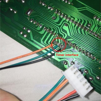
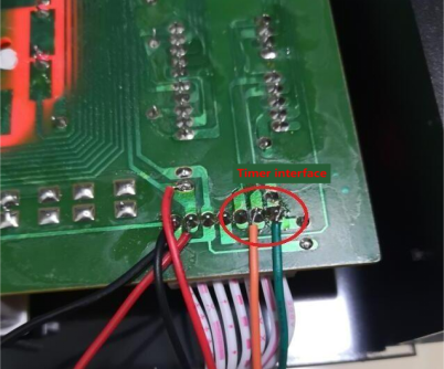
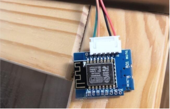
Continuing with the DIY process, the module uses the commonly used ESP8266 IoT module, with a total of four wires: one red wire for the 5V power line, a black wire for the ground, and green and orange wires for the clock and data lines. Solder the black, green, and orange wires to the calibration socket on the PCB, and solder the red wire to the DC socket. For electronic enthusiasts, this is not difficult and can be done in a few minutes.
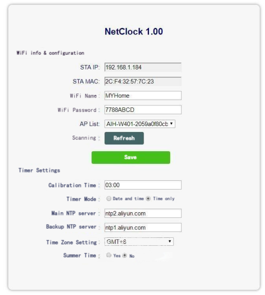
First, scramble the LED's time and date, then plug in the module, paying attention to the power direction. Turn on the LED clock's power, search for nearby WiFi on your phone, and connect to the network with SSID starting with NCLKxxxx without a password. After connecting, open the phone's browser and enter the address 192.168.8.1, which is the module's control page. In this page, fill in a few key data, with the most crucial being your home WiFi name and password. The module needs these to connect to the internet for time calibration to work. The base station can be automatically scanned and selected; if not, it can be manually filled in. Just choose the base station, input the password below, and save.
After about 2 minutes, the module will restart and automatically connect to the internet. If there's a computer at home, you can check the DHCP-assigned IP from the router, where hosts starting with NCLK are the calibration modules. Next time, you can use the IP displayed in DHCP to access the control page, which is more convenient. After setting, the phone can be switched back to the normal home WiFi. The phone is only used for the initial setup of the module's password, and a laptop can also be used.
There are several other calibration settings:
1. Calibration time, i.e., the time to calibrate the LED clock each day. The default is at 3 AM. If you don't need to modify it, keep the default value of 03:00. If you want to calibrate multiple times, you can write multiple times, separated by semicolons, such as 03:00;15:00, etc. Do not add a semicolon after the last time. The time is in 4 digits with a colon in the middle. You can write up to 24 time values. If you don't want the module to calibrate the clock, delete the default 03:00, leaving it blank. This way, it will only calibrate the clock once when the module is powered up, and it won't calibrate afterward, effectively controlling the module from working.
2. There are two calibration modes: date and time, and only time. You can try both. If the date data gets messed up after calibration, choose only time. For LED clocks that switch between displaying the Gregorian and lunar calendars, generally, only time is selected. Once the date is manually set, it generally won't go wrong. Only the hour, minute, and second data need calibration, and the date will change automatically.
3. NTP primary and backup servers currently use Alibaba's servers. If you have your own server, you can modify it.
4. Time zone and daylight saving time are set to Beijing +8 by default, with no daylight saving time. If used abroad or in other regions, you can set the local time zone and whether there is daylight saving time. This ensures the LED clock displays correctly based on the time returned by the network.
For these four calibration settings, under normal circumstances, there is no need to modify them, keeping the default values. Users only need to set two critical data: the WiFi access point and password.
The module calibrates the LED clock twice after power-up, at 15 seconds and 60 seconds, because some LED clocks play music for a while after power-up, rejecting calibration during this time. Therefore, calibration is done when the music ends to ensure everything is foolproof. If the WiFi password is correct, after about 2 minutes, you will see the previously scrambled time corrected, indicating that the calibration function is normal. From then on, it will automatically calibrate the clock at 3 AM every day.
If, after 2 minutes, the module's LED light goes out, but the LED clock's time hasn't changed, it may be that the green and orange wires are mixed up. Try swapping them and power up again for 2 minutes.
When not receiving the NTP clock signal, the LED on the module blinks for 1 second and goes off for 3 seconds, continuously flashing. After receiving the correct NTP time, the LED goes off to avoid being glaring at night.
The wiring positions in the pictures are for the calibration interface, generally with 3 reserved pins. If not, it shares with the setting key. The clock and data lines connect to the two ends of the setting button.


