
Discover the process of crafting a versatile yet uncomplicated load for electronic applications.
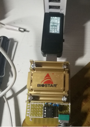
The design features a perforated board with an adjustable heatsink, utilizing a repurposed PCB as the foundational component.
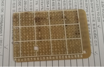
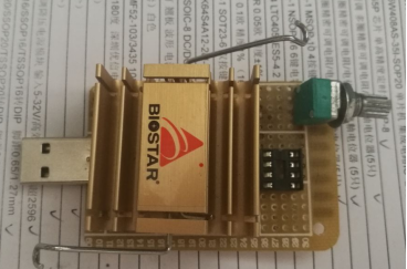
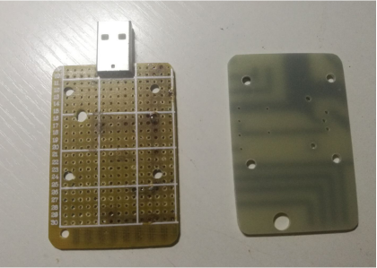
The assembly is straightforward—position the elements, establish the connections, and the setup is swiftly operational. In cases where power fails to reach beyond 500mA, a potential culprit could be the MOS. Consider replacing the 10N60 with a 75N75, as the former's DS resistance may impede current flow.
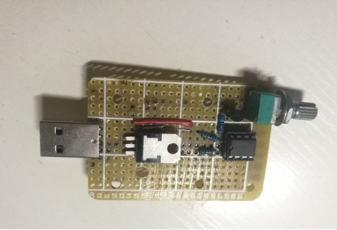
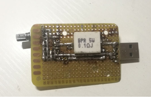
Enhance thermal management by applying silicon grease, and, for cooling, affix a 35X35 fan as a user-installed option.
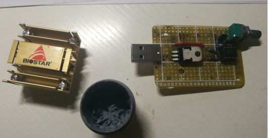
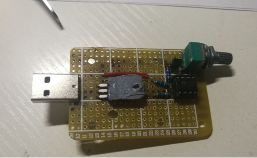
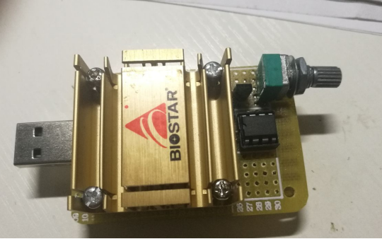
This charger incorporates protective measures, ceasing output if the current exceeds 2.6. Consequently, running at 2.5A for a minute results in significant heat buildup on the heatsink. To facilitate tasks such as measuring battery capacity, the addition of a fan is recommended. Presently, the setup is employed solely for short-term testing of charging cable currents.
Refer to the provided circuit diagram, capable of theoretically achieving an adjustable current exceeding 3A.
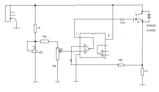
Although a fan is not currently integrated, the absence of one eliminates the need for an auxiliary power supply. Employing LM358, the system operates seamlessly within the voltage range of 3V to 30V.
For precise current adjustments, consider replacing the adjustable potentiometer with a fixed resistor ratio. This modification, achieved through a DIP switch, enables the customization of positive input voltages on the operational amplifier, allowing for the selection of multiple values.
This comprehensive guide not only elucidates the construction process but also highlights potential troubleshooting steps, making it a valuable resource for electronic enthusiasts and professionals alike.


