
If you possess three electronic devices operating on a 12V power supply, consider constructing a customized power distribution solution to consolidate their power sources. This entails crafting a power box that enables these devices to share a common power supply, with distinct channels catering to each load individually. Additionally, the integrated design of this power box incorporates a USB interface to address issues related to suboptimal charging currents and prolonged charging durations, particularly relevant for mobile phone chargers or power banks.
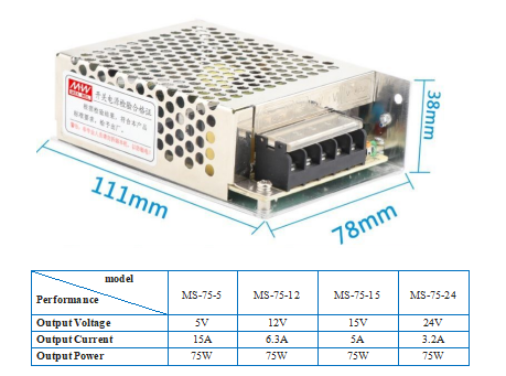
The respective output currents of the electronic devices are 3A, 2A, and 0.5A, supplemented by the phone charging port. A 12V 6.3A switching power supply with a capacity of 75W is recommended for this purpose.
For those lacking access to specialized machinery or facing challenges in metal casing fabrication, an alternative option involves utilizing a wooden enclosure.
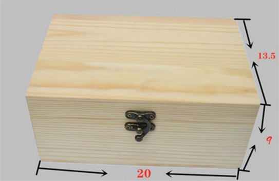
It is advisable to opt for a slightly larger wooden box to accommodate additional functionalities. This allows for the creation of a comprehensive power supply system where each channel can be independently controlled, enhancing flexibility and usability.
The construction process involves meticulous steps, beginning with component layout and panel arrangement. In the absence of Computer-Aided Design (CAD) expertise, software like Photoshop can be employed for visualization, as depicted in the accompanying images.
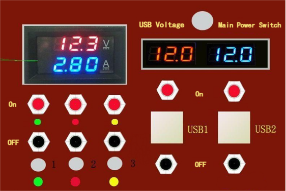
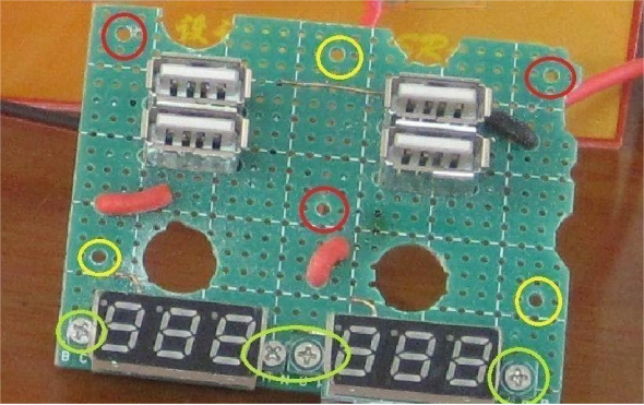
Precision drilling is crucial, particularly for the 2mm fixed holes of the low-voltage meter.
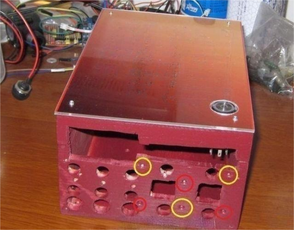
These holes are transitioned using a perforated board, camouflaged with a photograph, and ultimately covered with a transparent acrylic board. The color-coded circles facilitate alignment and fixation between the perforated board, wooden box, and transparent acrylic board
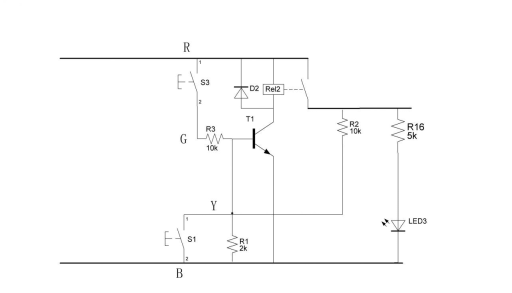
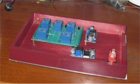
The control part is relatively easy, comprising five identical circuits. For USB power supply, a brief explanation: USB outputs 5V. If you use a simple 7805 integrated block to convert voltage, it consumes a lot of power. Additionally, the 7805 only provides 1A of current, resulting in a power consumption of (12-5)*1A=7W when fully loaded. This is wasteful, and the output current is too small. To output 2A current, you would waste 14 watts of power, affecting the normal operation of the circuit. Therefore, a DC/DC conversion circuit is chosen for its high efficiency, over 95%. The small circuit boards inside the cover in the image are the finished DC/DC conversion circuit boards.
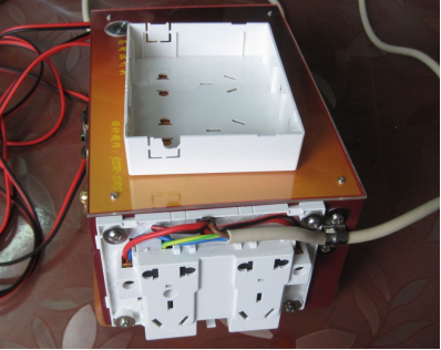
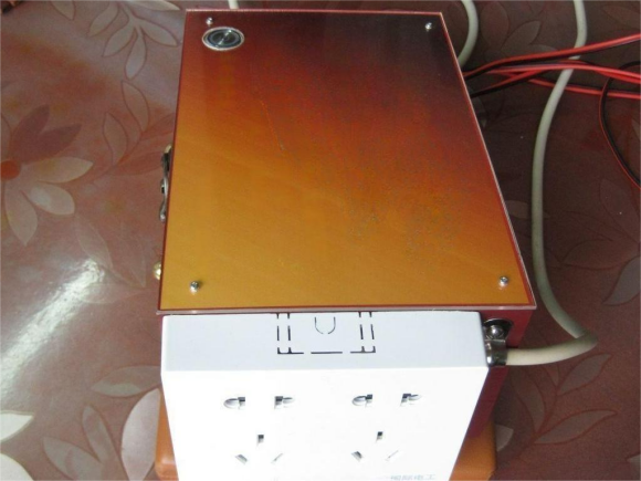
During the assembly phase, due consideration should be given to potential conflicts and additional features such as a 220V power socket. The integration of a 250V voltage switch, albeit increasing the overall dimensions, is strategically managed by incorporating a 2mm acrylic board on the panel to maintain uniform height.
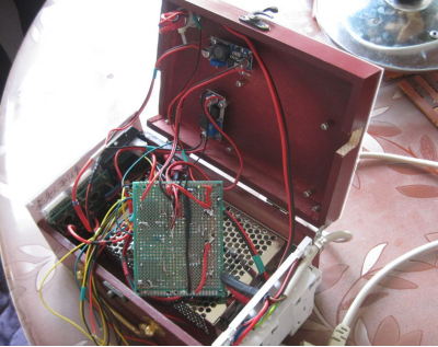
Connect the internal circuits, install the two boards, and the box is complete.
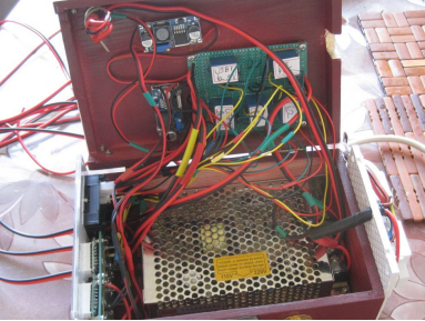
Upon completion, the wooden box is equipped with rubber pads to facilitate horizontal or vertical placement, enhancing versatility. A stylish copper handle is affixed to the opposing side when the box is positioned vertically, adding to its aesthetic appeal.
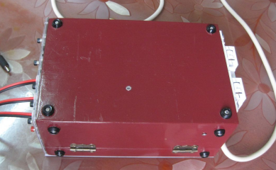
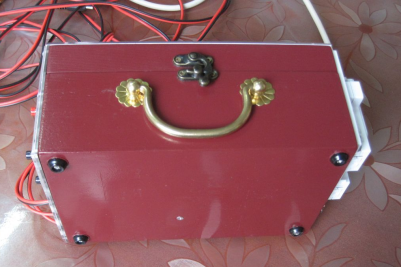
Photographs detailing the pre- and post-coverage of the 220V socket panel are included for reference.
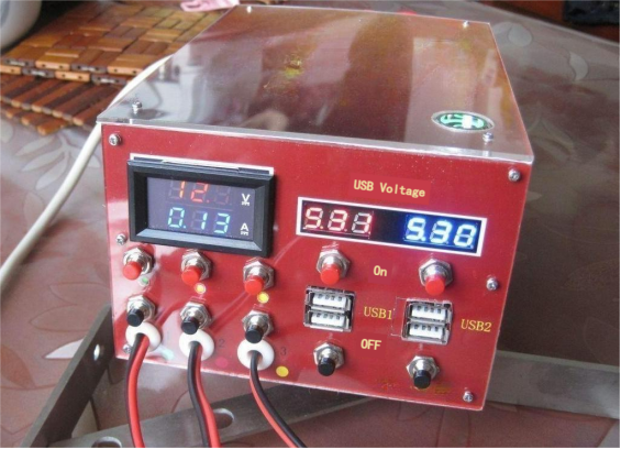
In operational scenarios with all power sources activated, the calculated power consumption is 12.5V0.13=1.625W, accounting for relay and control circuitry.
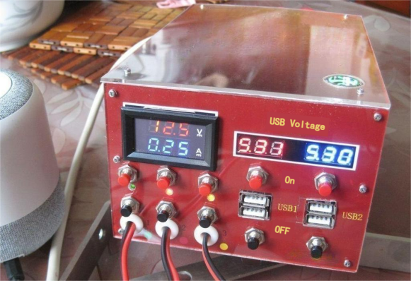
This consumption increases to 12.5V0.25=3.12W with the inclusion of a small speaker.
In summary, the production process, marked by iterative adjustments, underscores the importance of strategic planning. Future refinements are recommended, including the adoption of plug-in 220V input power lines to streamline wiring and enhance portability.


