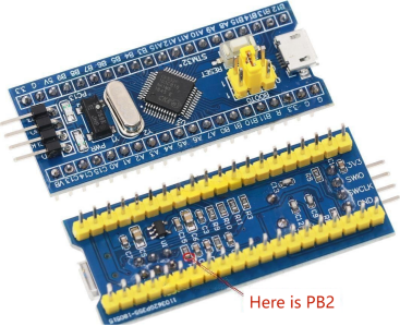
Unlock the potential of seamless integration with a single STM32F103C8T6 development board and your laptop's built-in keyboard. Facilitate this by connecting the keyboard's 8x16 matrix to the development board's PA0PA7 and PB0PB15 ports.
While PB2 remains unexposed on the board, it's noteworthy that BOOT1 is intricately linked to PB2 with a resistor. The actual PB2 is explicitly indicated in the accompanying image.

Let's commence with an introduction to the firmware components:
· stm32f103.keyboard8x16.bin (standard keyboard firmware)
· stm32f103.keyboard8x16.matrix.bin (matrix testing firmware)
Upon flashing any firmware and establishing a USB connection, you'll observe the recognition of a keyboard device. Illuminating the LED on the development board can be effortlessly achieved by engaging the Caps Lock key.
In the case of flashing matrix.bin and connecting to a computer, opening Notepad and positioning the cursor triggers the display of matrix row and column numbers corresponding to the short-circuited connections between PA0PA7 and PB0PB15.
For enhanced ease of assembly, the removal of vertically mounted pins from the development board is recommended. Even with only BOOT0 and BOOT1 soldered, SWD port downloads remain feasible.
Securing a cable socket proves challenging; however, the use of thin double-sided tape to affix tinned enameled wire to pin contact points, along with screws and hard plastic pieces, facilitates a secure connection. The addition of sponge or elastic pads ensures optimal contact stress.
Isolating the thin standalone laptop keyboard for attachment to wooden or acrylic boards involves a simple slot cut into the board to accommodate the STM32 development board.
Delving into the underlying principle: Typically, laptop or desktop keyboards share a uniform 8x16 matrix, albeit with variations in wire sequencing. In the absence of documentation, discerning and categorizing the wires into 8 rows and 16 columns (or more) poses a challenge. Elevating the wires slightly aids in identification. Once identified, commence connecting one row and one column, utilizing Notepad or keyboard testing software for verification. The initial attempts may require additional iterations, but proficiency increases with subsequent connections.
Supplementing this setup are three additional open-drain output states:
· PC15 NumLock
· PC13 CapsLock
· PC14 ScrollLock
This meticulous approach results in the creation of an ultra-thin and compact keyboard solution, poised for seamless integration and optimal performance.


