The SR501 infrared motion sensor module is available in two variants, denoted by green and blue boards, both subject to the same modification procedures outlined in this guide.
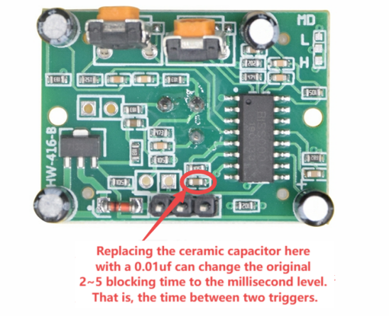
Adjusting the lockout time, the duration between consecutive triggers, is conventionally recommended at 2.5 seconds. However, real-world lockout times typically range between 3 to 5 seconds. For applications such as sensor-activated lighting, this timeframe may be deemed excessive. Modifying the lockout time has the potential to impact interference resistance. It is important to note that the information presented here is intended for testing purposes and should be used as a reference. The modification process is visually depicted in the accompanying diagram.
Upon comparing human body sensing modules SR501, SR505, and SR602, it is apparent that the SR501 module is better suited for DIY projects.
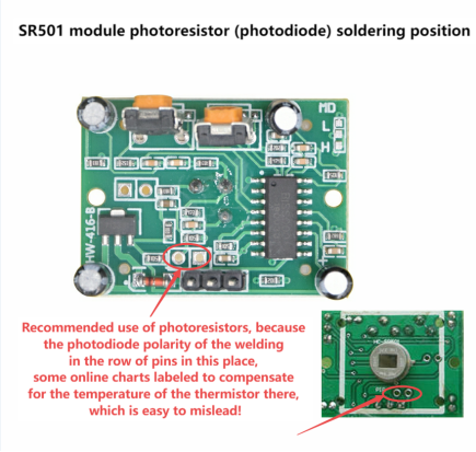
Both SR505 and SR602 modules may exhibit spontaneous triggering and pose challenges in delay adjustments. Notably, SR505 lacks the capability to directly solder a photosensitive resistor for day-night differentiation, making it less user-friendly, especially for beginners. Integrated motion sensor nightlights are commonly unsuitable for yard lights due to their low power output and limited sensing range.
Solar-powered motion sensor lights typically have fixed delay periods, approximately 20 seconds, rendering them unsuitable for specific applications, such as sinks or toilets.
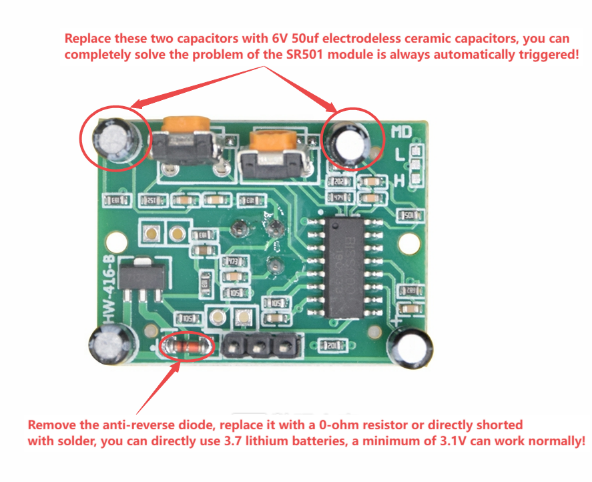
The SR501 module, characterized by its affordability and comprehensive functionality, emerges as a prime choice for experimental projects. It is worth noting, however, that SR501 modules may experience unexplained automatic triggering events.
The following are practical applications and illustrative images for SR501 modules:
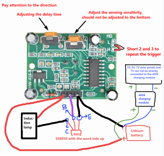
Standard Operation: Without any modifications, the SR501 module, when coupled with an S8050 transistor, operates within a voltage range of 4.5V to 20V, delivering an output current ranging from 200mA to 500mA. It is crucial to recognize that an input voltage below 4.2V may result in continuous triggering.
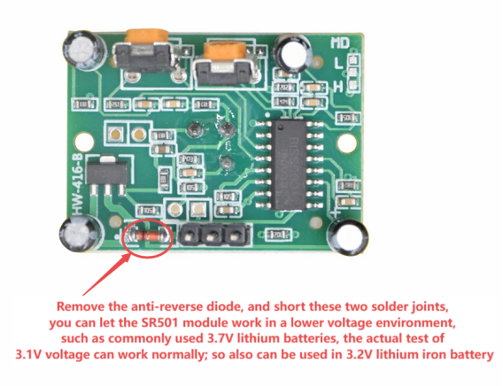
Low Voltage Operation: For direct usage with a 3.2V to 3.7V lithium battery, the modification involves removing the reverse-biased diode and short-circuiting two specific solder points, as illustrated in the provided diagram.
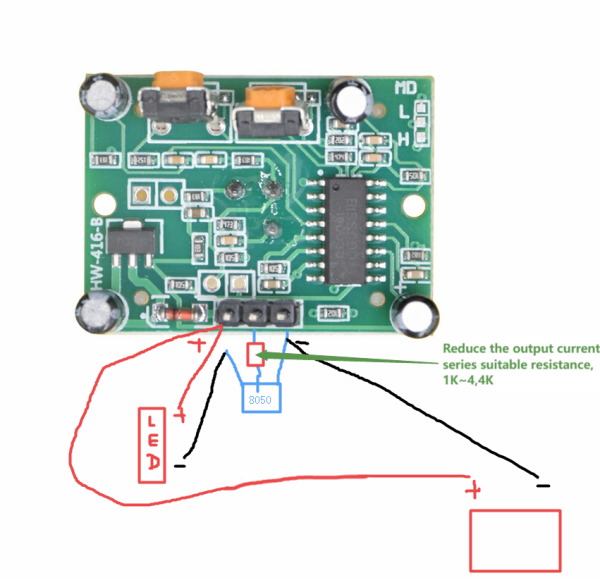
Output Current Reduction: To decrease the output current, a resistor can be introduced in series between the SR501 module's output pin (middle pin) and the base (B) of the S8050 transistor. This adjustment proves beneficial, especially when utilizing LED beads for a nightlight. The corresponding diagram offers clear guidance.
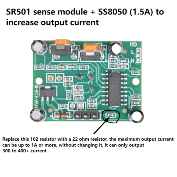
Output Current Enhancement: For those seeking an augmented output current, swapping the existing 102 (1K) resistor at the output terminal with a 22-ohm resistor, as depicted in the diagram, achieves an output current of approximately 1000mA. This modification also extends the module's operational threshold to dimmer environments.
