
To modify a 936 soldering station, here's what you should do:
The main task is to install a 12864 serial port screen, using an STM32F103RC as the main controller, to display temperature settings and real-time temperature, as shown in the diagram below.
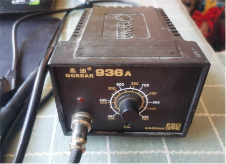
It's this soldering station:
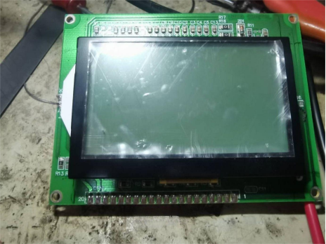
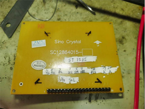
This is the serial port screen, it can be powered by 3V or 5V, and the CS can be directly connected to VSS.
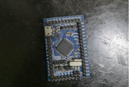
This small board is the core board of the STM32F103RC.
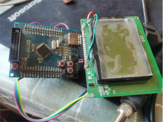
First, conduct experiments with a test board and the 12864 screen, write the program, debug it, and finally install the board and screen onto the 936 soldering station.
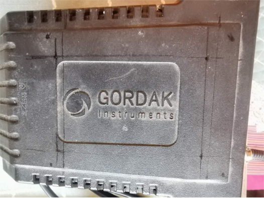
First, open the cover of the soldering station to measure the size accurately.
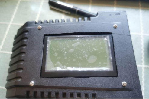
Pure manual slotting may look a bit messy and requires caution.
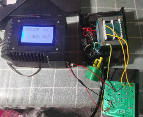
During program debugging,
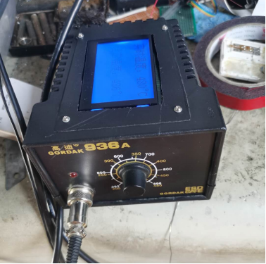
After debugging is complete, proceed with the installation.
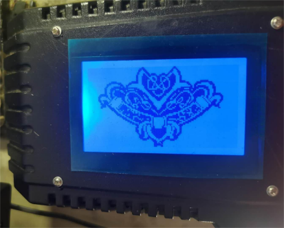
The startup screen is similar to the one shown in the image above.
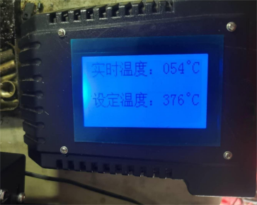
After setting the temperature, the real-time temperature is rapidly rising.
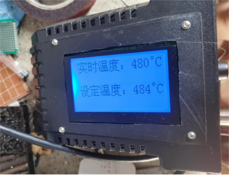
It reaches the set temperature
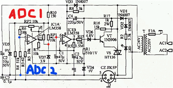
The circuit diagram can be referenced from the above image, with two ADC test positions marked on the diagram. The two red dots represent ADC1, and the two blue dots represent ADC2.
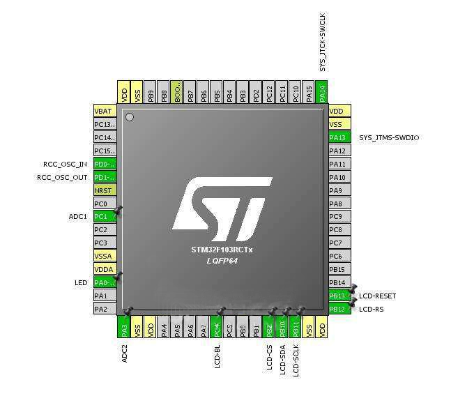
Finally, here's the connection diagram for the STM32.
You can find the program below:
ALIENTEK+MINISTM32+Experiment 15+ADC Experiment.zip


