Following the previous DIY Guide: Convert GREENTEK GU10 to E27 Spotlight, this article will be about converting to a wide-range low-voltage DC spotlight. It operates within a power range of 12-48V (with redundancy, constant current for step-up/step-down), and features touch dimming.
To achieve wide-range low-voltage, constant current driving, and touch dimming, the first technical point to address is determining the voltage range.
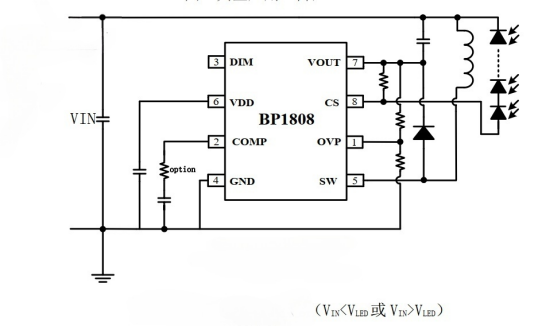
The LED chip operates at around 36V. If the power supply voltage range needs to cover both ends of this 36V, then a step-up/step-down constant current driving chip is necessary. In this article, we're using the BP1808 chip from Bright Power Semiconductor (BPS).

The supply voltage ranges from 3-60V, which is slightly different from the desired 80V. However, considering that the voltage of electric vehicle batteries gradually decreases to a maximum of 48V, a 60V voltage is sufficient. Additionally, it supports both analog and PWM dimming, providing two options for touch dimming.
Regarding the power supply input method, the existing GU10 interface can be directly utilized by clamping with alligator clips. However, since the GU10 interface cannot distinguish between positive and negative poles, a bridge rectifier is added at the input stage. To reduce the power consumption of the rectifier bridge, a Schottky diode SS36 is used as the rectifier diode. To prevent the input voltage from burning out subsequent circuits, a varistor 7D560 and a fuse are added for protection at the input.
The second technical point concerns the selection of the touch dimming scheme.
RONG HE provides two touch dimming chips: RH6616 and RH6618. Both have identical functions and fully compatible pins, with the only difference being that the PWM pulse output of 6616 is 4KHz, while that of 6618 is 25KHz. Since higher PWM pulse frequency allows for smaller required filtering capacitors and lower ripple voltage on the LED chip, 6618 is preferred. However, since the maximum PWM pulse supported by BP1808 is 10KHz, lower than 6618's 25KHz, 6618 can be initially used, and if it doesn't work, 6616 can be tried.
The third technical point addresses the power supply of the touch dimming chip.
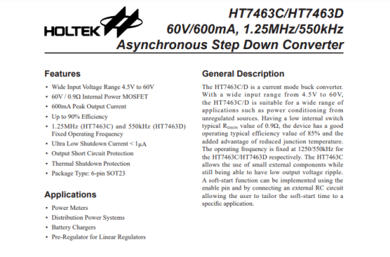
As the touch chip requires low-voltage power supply, with an operating voltage of only 2.4-5.5V, a step-down circuit is needed to reduce the input voltage to a suitable value. Since the voltage difference is significant, using an LDO is not practical, despite the low power consumption of the touch chip. Therefore, a low-power DC-DC circuit is more suitable. HOLTEK's HT7463 power chip can be used.


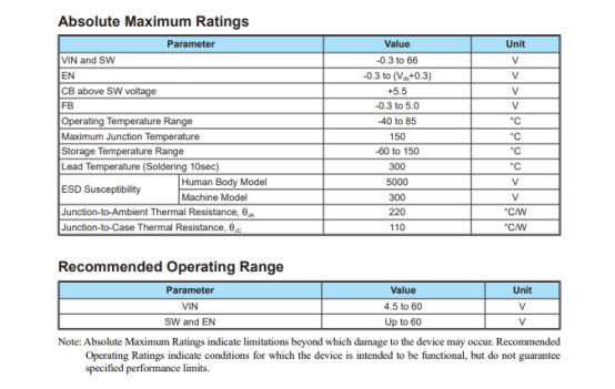
With an output current of 600mA, HT7463 is capable of driving the touch chip. The circuit scheme is then finalized: a 56V varistor and fuse for overvoltage protection at the input stage, SS36 Schottky diode for bridge rectifier output, one side of the output voltage goes to BP1808 to drive the LED chip, and the other side is converted to 5V by HT7463 to power RH6616, whose PWM signal adjusts the dimming of BP1808.
However, there are some shortcomings to address:
1.HT7463 remains in operation after power-on, with a relatively high standby current (tested standby power consumption of approximately 0.12W).
2.The maximum input voltage of the circuit is limited by the HT7463's voltage limit of 55V. For safety, the maximum input voltage is set to its maximum rated voltage of 52V. However, a fully charged 48V lead-acid battery may have a voltage between 54-56V, which could potentially damage the HT7463 or varistor.
3.The bridge rectifier reduces the efficiency of the circuit, and the lower the input voltage, the larger the bridge arm circuit and the greater the power consumption on the bridge, resulting in lower efficiency.
Analysis of the shortcomings:
1.Since there are no internally integrated batteries, removing the battery when not in use for a long time is acceptable, and in the short term, a standby power consumption of 0.12W is acceptable.
2.A 48V voltage exceeds the human body safety voltage, so the probability of use is low. Additionally, in the unlikely event of using a 48V battery, as long as the battery is not fully charged, there should be no problem (the battery only needs to hold very little charge to reduce the voltage below 52V).
3.Increasing the supply voltage appropriately, such as 24V, can improve the circuit efficiency. Furthermore, if the input positive and negative poles are clearly identified, the bridge rectifier can be removed to improve efficiency.
Alright, that's it for this article. The next DIY one will delve into circuit design.


