
How to Build a 10A Load with Parts?
You will need an LM324 load circuit, simplified with limit resistors and filter capacitors, among other components. If you don't have a TL431, you can use a 78L05 as a reference. Since the design is simplified, it won't be highly stable, but the emphasis is on using fewer and easily available parts.
Circuit:
Green lines intersecting without a red dot means they are not connected.
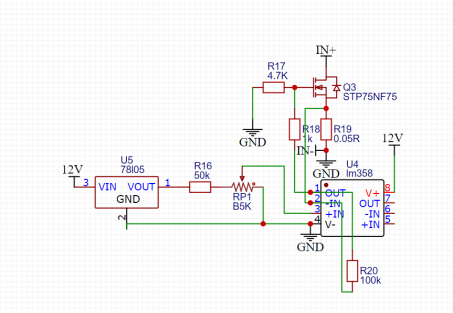
If you don't have a sampling resistor, you can temporarily use a 10A fuse and fuse holder instead. Testing showed that a single fuse has an 8-milliohm resistance, and with the holder and wires, the resistance is around 40 milliohms. Therefore, the maximum current slightly exceeds 10A.
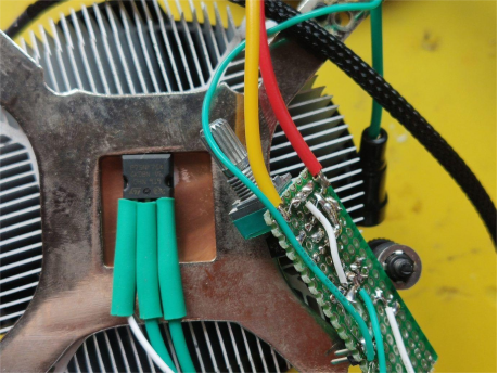
The MOSFET used is the STP75NF75. Tests show it performs well, with a single transistor handling up to 150W without issues. The heatsink used is from a Ryzen stock cooler, mounted using a base bracket.
Testing:
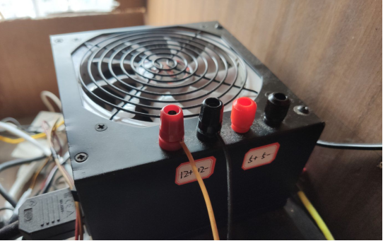
An Antec VP450 was used for testing. Without modifying the adjustable voltage, the wires were directly pulled out to provide two voltages: 12V and 5V.
1. At 12V, with two meters connected in parallel, the actual current limit slightly exceeds 10A, as one meter was not enough.
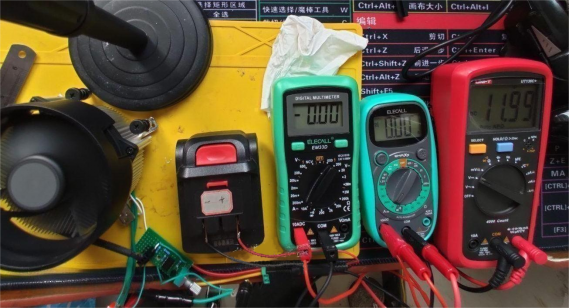
At 14.5A, there was a 1V drop at the terminals.
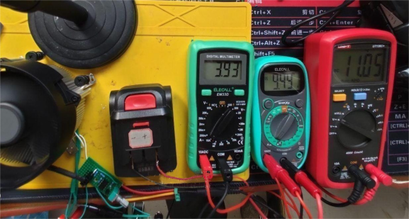
2. At 5V
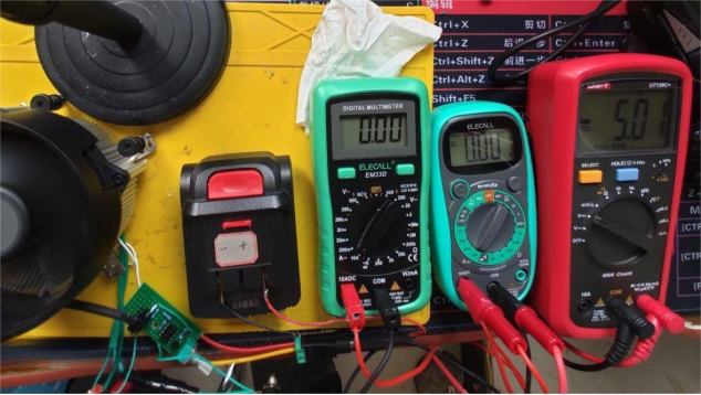
At 14A with acceptable voltage drop, indicating the VP450 is a solid choice for a high-current power supply.
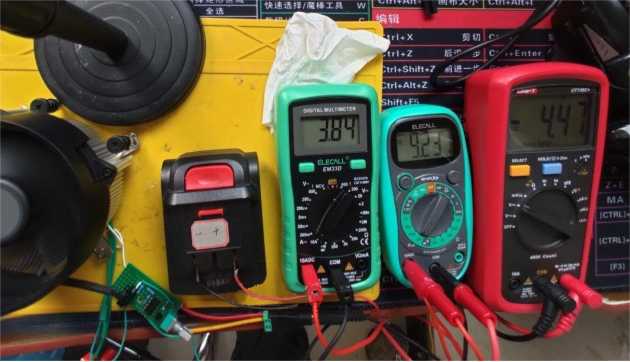
After testing, the fuse holder might deform due to the heat generated by 14A current, as even with 40 milliohms resistance, there is a 7-8W power loss. For stability, it’s recommended to use a high-power cement resistor for sampling, preferably a 5W resistor with a heatsink. Alternatively, you can reduce the value of the sampling resistor or increase the resistance of R16.


