Do you want to DIY a 1.5V single-tube radio? You can reference this article.
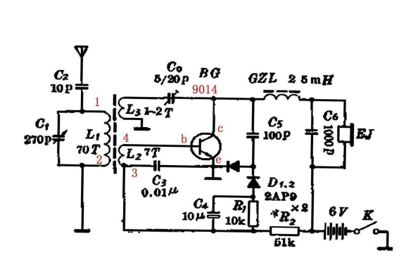
Using a crystal high-frequency tube serves both as high and low-frequency amplifier, dual-use, alongside a regeneration and multiplier detection circuit. This enhances the radio's sensitivity, selectivity, and stability. The most classic is the 636 single-tube radio. With the introduction of silicon tubes, stability has improved, with higher beta values. Some use silicon tubes for better reception results.
This article designs a versatile PCB circuit board based on different combinations of regeneration, multiplier, and silicon-germanium mixtures, meeting various circuit requirements. It can achieve a full-germanium tube radio, like the classic 636 circuit; can add different regeneration methods on the 636 circuit basis; can mix silicon and germanium; or can use all silicon tubes. However, currently, the all-silicon tube performance yields more satisfactory reception results. In the medium-wave environment, using 9014 + 4148*2 + 32-ohm low-resistance MP3 earphones + 1.2V voltage, adjusting regeneration properly yields excellent results, essentially capturing most of the stations DeSheng 2P3 can.
Follow along for the operation
1.The overall layout is based on the 636 single-tube regenerative radio, with optimizations in certain areas:
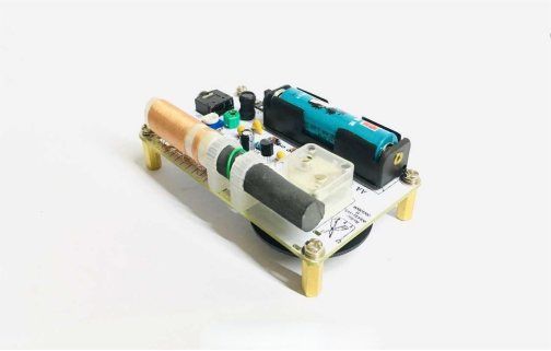
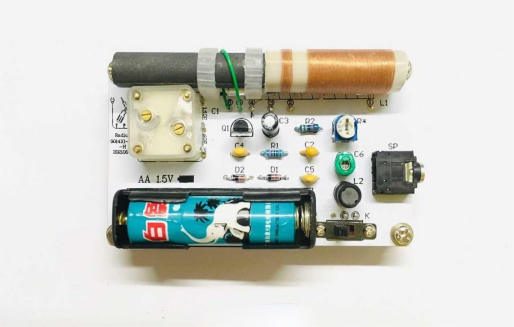
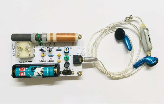
2.The magnet rod is moved to the top, as its proximity to the desktop affects the Q value during radio placement. The classic 636 uses a magnet rod with a diameter of 10mm and length of 70mm. Based on PCB design, an 80mm magnet rod is used, with the coil placed next to one side of the magnet rod to effectively enhance radio sensitivity.
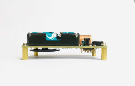
3.The battery is positioned at the bottom. A single No. 5 battery box is used, suitable for 1.2V batteries or 3.7V lithium batteries. With 9014 silicon tubes, 1.2V is sufficient. The radio shown in the figure uses an AA No. 5 battery.
4.The headphone jack is relocated to the lower left corner, using a 3.5mm headphone socket compatible with commonly used MP3/mobile 32-ohm headphones for good sound quality. When not in use, the headphones should be unplugged; battery consumption is minimal and can be ignored.
5.Regarding GZL issues, a 2.5mH ready-made inductor can be found online, providing excellent performance. The positioning of GZL is critical; it must be far from the magnet rod to avoid squealing.
6.Variable capacitors: In terms of performance, CBM223p is quite effective, especially with its built-in fine-tuning, useful for adjusting medium-wave frequency coverage. It is recommended to use 140p + 60p = 200p in parallel.
7.Dial indicator: The original 636 dial had a raised indicator in the upper right corner, but right-hand operation often blocked the reading, necessitating some adjustment.
Main component requirements:
1.Magnet rod: 10mm diameter * 80mm length, with two white plastic support brackets.
2.Coil: Tuned with 0.07 * 7 silk-covered wire, 80 turns, with 8 coupling turns. The entire coil is wound on a 10mm bubble tea straw.
3.Coil connections are sequentially labeled 1, 2, 3, 4, and connected as follows: the first end is soldered to the variable 140p or 60p, the second end is connected to the variable center pin (ground), the third end is soldered to a 10K resistor, and the fourth end is connected to the BG b-pole.
4.Variable capacitor: CBM223P, used in parallel as 140/60p to form 200p.
5.9014 beta values range between 280-320.
6.D1D2: IN4148, two pieces.
7.GZL: Ready-made I-shaped inductor, 2.5mH.
8.Headphone jack: 3.5mm stereo headphone jack, without a switch, minimal power consumption when unplugged, almost negligible.
9.Bias: 20K + 200K adjustable resistor.
10.Regeneration: This is the soul of the single-tube radio. There are many regeneration methods; experts understand them well. Here, a short wire is soldered to the BG c-pole for simple and efficient adjustment of regeneration at different positions.
Everything is soldered onto a 90 * 56 * 1.6mm PCB board. After soldering, install the dial, insert the battery, plug in the headphones to receive stations, adjust bias between 0.8-2mA for suitable sound (too high bias distorts strong station sound). Normally, regeneration isn't needed; sensitivity slightly decreases at the high end. Adjust regeneration according to point 9 above if high-end medium-wave stations are present. Finally, place everything in a wooden box, recalibrate the frequency with the dial, and secure the back panel with screws. This completes the single-tube regenerative radio.
Testing:
1.Bias: Best around 0.8-1.2mA; if regeneration is adjusted properly, even 0.5mA is excellent. This confirms the basis of previous experience. Some prefer louder volume; bias around 3mA can be "ear-shaking," causing distortion. After testing, using 1.2V batteries and 20K + 200K adjustable resistors, or using 3.7V batteries, switch to 150K + 200K adjustable resistors.
2.Regeneration: Greatly enhances selectivity and sensitivity. Regeneration adjustment for this single-tube machine is straightforward; a soldered wire adjusts regeneration, with position affecting strength. Different medium-wave environments may require additional adjustments.
3.Headphones: MP3 or mobile headphones work well, requiring moderate volume for good sound quality.
4.Frequency Coverage: Tuning 80 turns as per main component requirements should cover most medium waves. Adjusting both variable fine-tunings outwards allows for higher-end station reception.
5.Directionality: Magnet rod radios exhibit directionality, greatly influenced by indoor versus outdoor medium-wave environments. For instance, concrete pillars indoors improve signal; affecting regeneration.
Overall, satisfactory results highlight low resistance, low voltage, and low bias features.
Radio schematic for silicon single-tube machine
