
If you're interested in building your own small SSB QRP shortwave radio, this article is a must-read.
Here are some reference parameters:
· Design parameters for the pocket-sized shortwave SSB transceiver KN-BOX:
· 40-meter amateur band (tested at 7045-7070KHz)
· Operating modes: LSB/CW
· Output power: approximately 10 watts
· Transmission spurious: better than 40dB
· Receiving sensitivity: 1uv/10db
· Power supply: 13.8V/3A
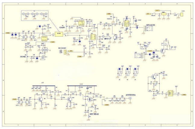
Circuit diagram:
You can choose the crystal oscillator yourself. One option is a 4MHz intermediate frequency with an 11.059MHz local oscillator. Another option is a 4.915MHz intermediate frequency with a 12MHz local oscillator. Both can work in the 40-meter band.
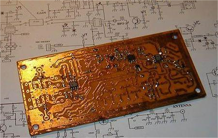
Start by assembling the low-profile SMD components.
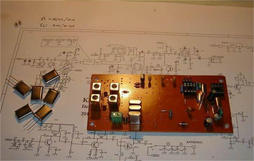
Next, move on to the taller through-hole components. There are several crystals: three for the local oscillator, six for the SSB narrowband filter, and two for use as filters and BFO.
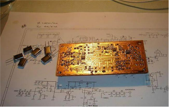
Install the relay for transmit/receive switching.
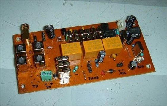
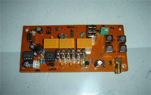
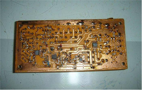
Testing:
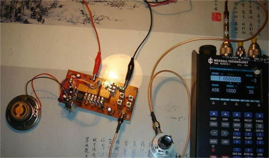
Use an RF signal generator to send RF signals to the antenna. Of course, this signal needs to be attenuated first. The attenuator setup is as follows: Two fixed 20dB attenuators + one adjustable 0-70dB attenuator, providing attenuation from -40dB to -110dB.
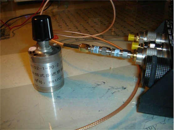
The reception test is quite good. The signal generator emits an RF signal at 7050KHz.
Once the main control board is finished, it can be installed in the chassis. This includes an amplifier previously made, with a final stage push-pull output using two 2SC2078 transistors, expected to output over 5W.
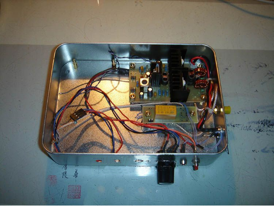
The amplifier board and the transmit/receive switching relay next to it.

Since the amplifier board requires 13.8V and the main control board requires 9V, an LM7809 regulator is needed to convert the power supply to 9V for the main control board.
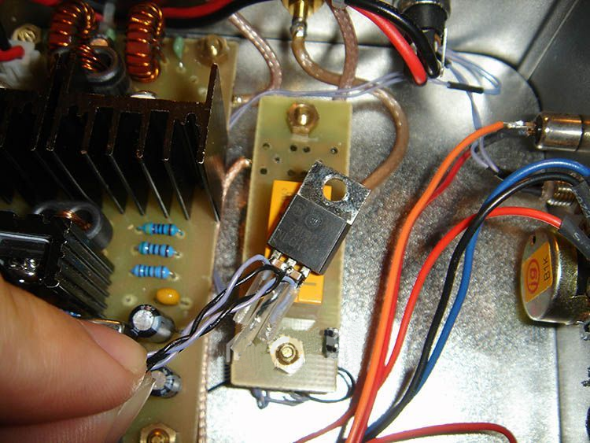

Assemble everything.

With the cover on, the build is basically complete. Both transmit and receive functions are working normally. Only the gain potentiometer, microphone, and headphone jacks are left to be installed, which can be completed later.


