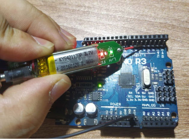
For those who frequently work with microcontrollers and Arduino, it is often necessary to check the output state of I/O ports. A logic probe can provide a general understanding of the output status, making it quite convenient. You can design a simple circuit that runs on battery power, suitable for 5V and 3.3V circuit boards. It can detect high and low levels, AC and DC signals, and estimate the duty cycle of high levels and the frequency of AC signals.
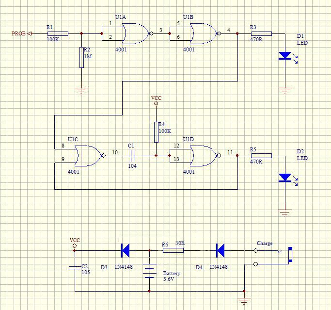
The circuit uses a CD4001 NOR gate. When the probe input is high, D1 lights up; the larger the high-level duty cycle, the brighter D1 glows. U1C and U1D form a monostable circuit; when the output signal is AC, D2 lights up, and within a certain range, the higher the frequency, the brighter D2 glows. You can adjust C1 and R4 to set the maximum frequency detected. D3 is included to reduce the operating voltage, preventing potential issues when detecting 3.3V circuits. Charging uses a 5V power supply, and D4 and R6 form a simple charging circuit. The static current of the CMOS circuit is very low, so there is no need to add a power switch.
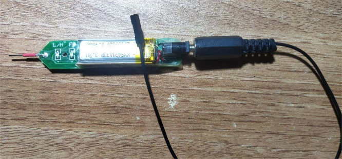
The circuit is designed to be simple and practical. If you don't have suitable transparent heat shrink tubing, you can use transparent tape instead.


