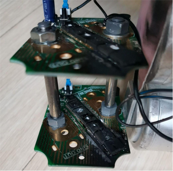
How to measure various waveforms of the spot welder control board using the DSO068 oscilloscope? If you're interested, keep reading.
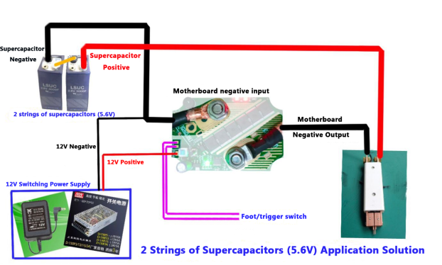
The spot welder setup is illustrated below: it uses three capacitors in series, and charging is done through a 12V adjustable step-down to allow for flexible voltage adjustments.
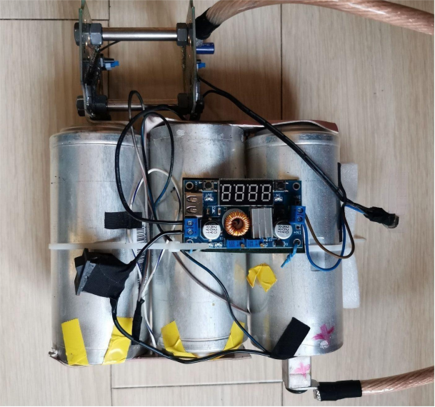
The actual setup is as follows: two boards are connected in parallel using double-headed bolts, ensuring that the current is fairly balanced. The MOSFETs' gate terminals on both boards are connected with wires. After verifying that there are no issues during the small current tests, we can proceed to large current tests.
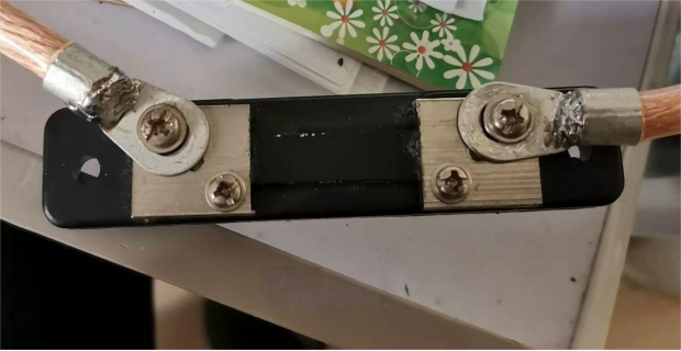
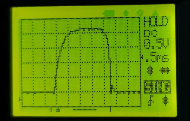
The output line of the spot welder is directly connected to a 50A ammeter shunt, with a shunt resistance of 1.5 milliohms. By measuring the waveform (voltage) across the shunt, we can estimate the actual current (though this might not be entirely accurate, it serves as a reference). We can then calculate the resistance of different components by analyzing the waveforms at various points on the spot welder.
Here are the shunt waveforms and calculated currents at different capacitor voltages:
Shunt waveform shows 950/1.5 = 633A at a capacitor voltage of 2.77V.
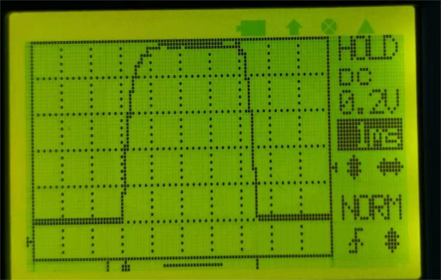
At 4.53V, the calculation shows over 1000A.
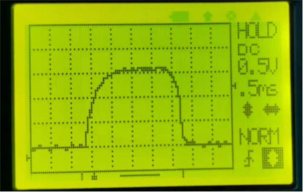
The resistance calculations for the positive lead and control board are as follows:
Positive lead resistance is calculated at 0.41 milliohms.
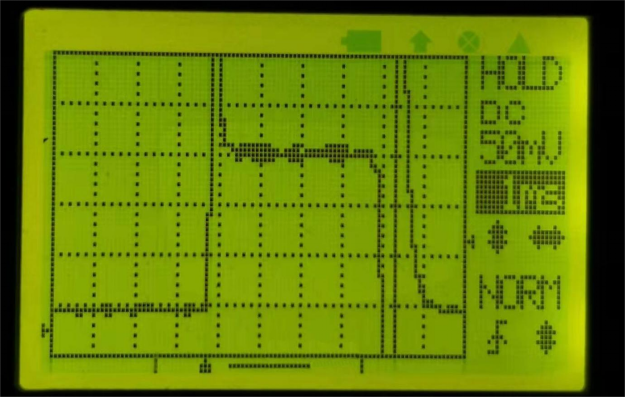
Resistance from the capacitor's negative terminal to GND OUT is 0.62 milliohms.
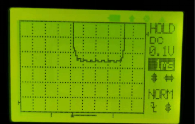
The combined resistance of the positive and negative leads plus the control board is approximately 0.41x2 + 0.62, leading to an estimated internal resistance of the three capacitors around 1 milliohm, with additional contact resistance.
Based on the above voltage and current calculations, the total internal resistance of the shunt circuit is about 4.5 milliohms. When the capacitor voltage is at 6.06V (calculating a current of 1400A), it automatically ran for a period (this board can perform automatic spot welding, triggering every 2-3 seconds). We found that, apart from the shunt gradually heating up, the temperatures of other components, like the MOSFETs, remained relatively stable, indicating that 1400A should be safe.
At 6.06V, the calculated current is 1400A.
Feel free to measure the internal resistance of the control board again as needed. That's it!
