If you've listened to small digital amplifiers for a while and miss the sound of analog amplifiers, then you can follow this guide to build a small amplifier with USB playback, FM radio, and Bluetooth capabilities.
This project involves dismantling the power supply of a TDA7439+LM4766 unit and reusing the casing of an old headphone amplifier. The amplifier and preamp sections are based on the TDA7439+LM4766, the USB playback and Bluetooth functionality is provided by a BT401 module, the FM radio uses an RDA5807M, and the control is managed by an STM32F030. The flash storage is a W25Q128, and the display is a 2.4-inch SPI LCD. Power is supplied by two 24V switch-mode power supplies. If the machine doesn't overheat during testing, you can temporarily skip adding cooling holes to the bottom and rear panels. Later, you can decide whether to add them based on actual usage.
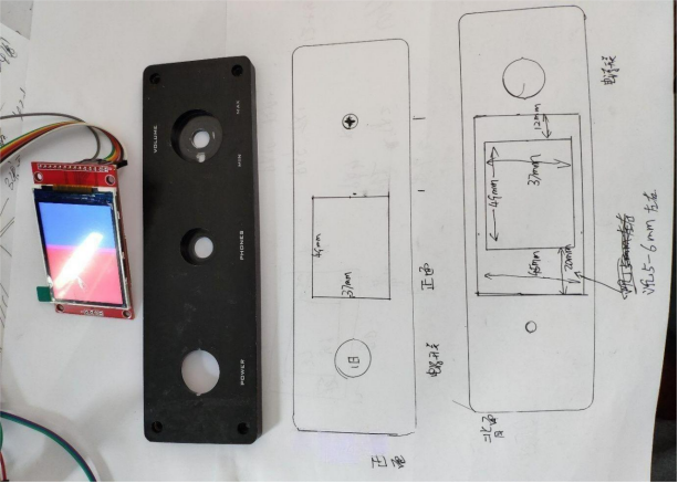
The casing used for this project is an old headphone amplifier casing. This time, the front panel needs to accommodate the LCD display. Below are the images of the case design and the finished panel.
The following is the original front panel, and the dimensions of the window are marked on the paper.
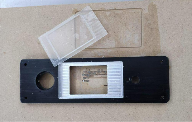
The processed panel turned out well.
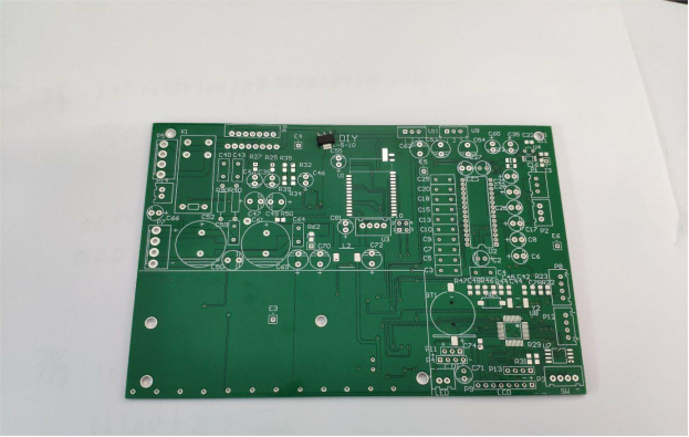
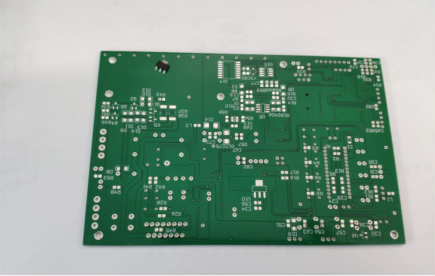
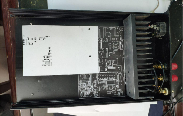
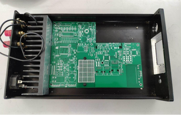
Below is the PCB design. Since the PCB is large, it was split into two sections for prototyping. If the TDA7439 malfunctions after the new board is installed, it may be difficult to replace due to the double-sided design, and since there was an error in the initial PCB design, the only solution would be to redesign the PCB and reorder the prototype. This would involve changing the preamp to a surface-mount TDA7439DS and repositioning the components accordingly.
Below is the first PCB prototype.
Here is the BT4010 Bluetooth module.
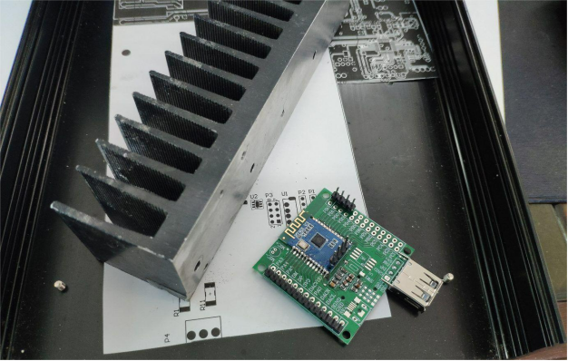
Next is the second PCB prototype.
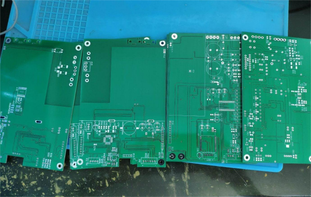
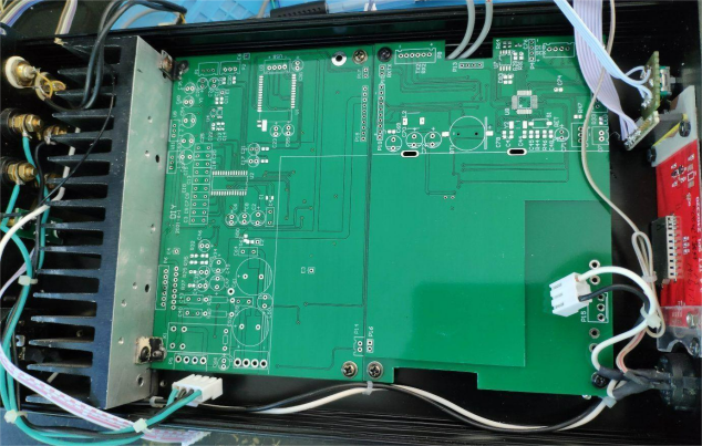
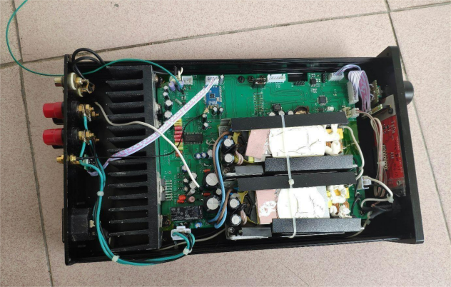
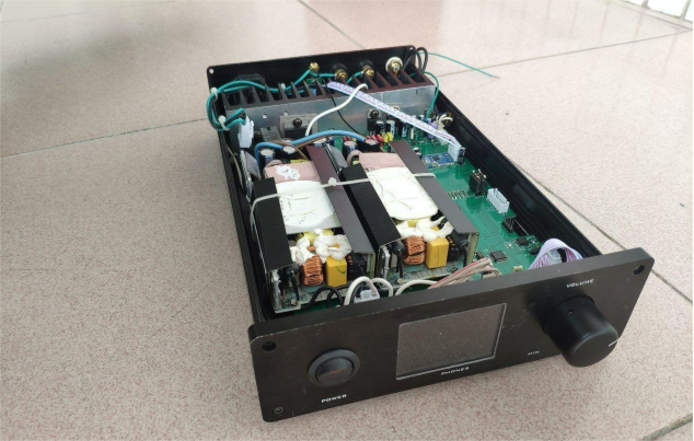
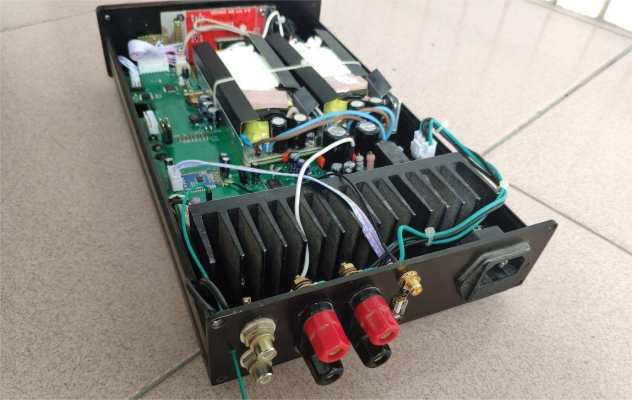
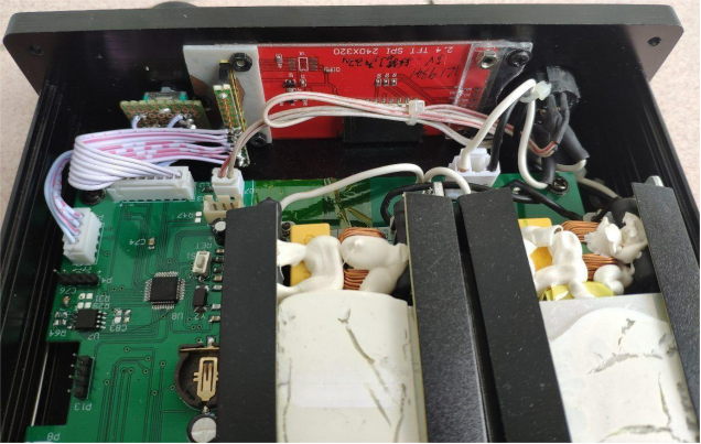
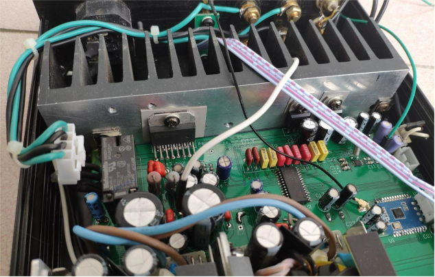
Here are the completed product images, including internal views.
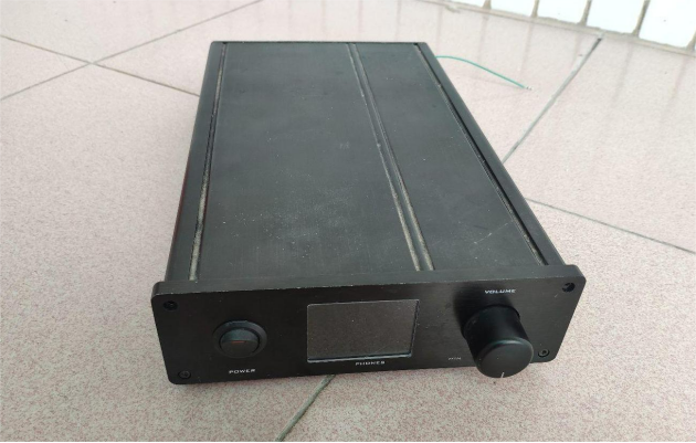
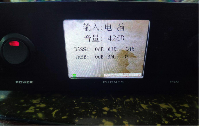
Here is the working interface screenshot.
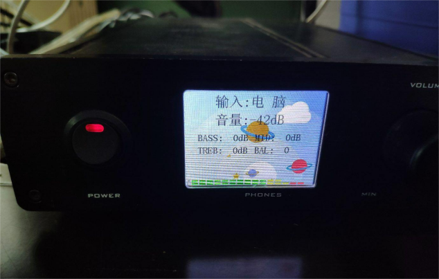
The following image shows part of the interface after the background image has been replaced.
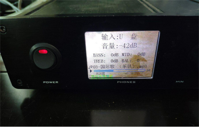
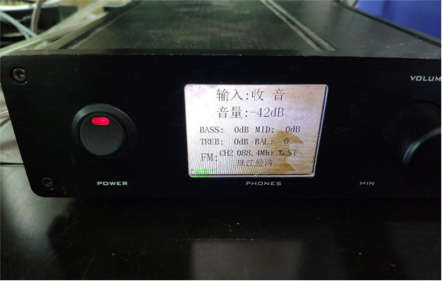
This is the interface for adjusting gain and other settings.
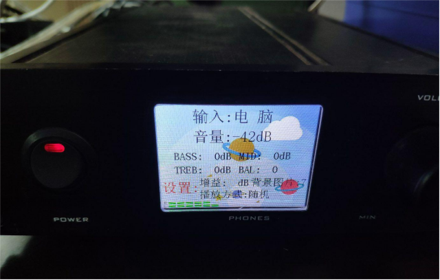
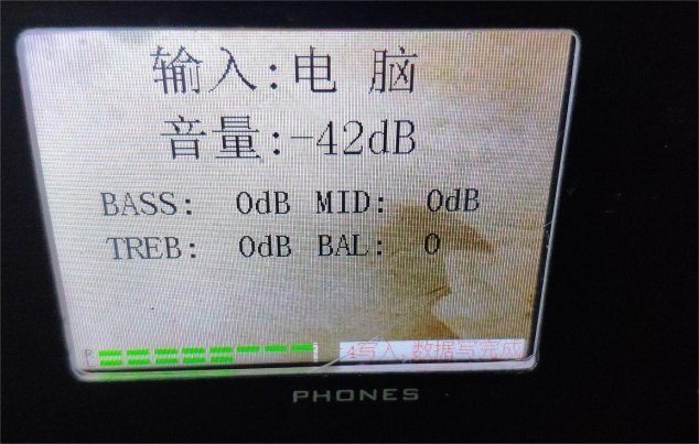
The following image shows the interface on the device. The text on the screen doesn't refresh during writing to prevent interference with the writing operation. The status text is displayed using the microcontroller's character set, which does not interfere with the writing process. After the writing is complete, the screen refreshes, and the status text may not be fully displayed.
