If you're interested in making a ZVS (Zero Voltage Switching) heater, take a look at this article.
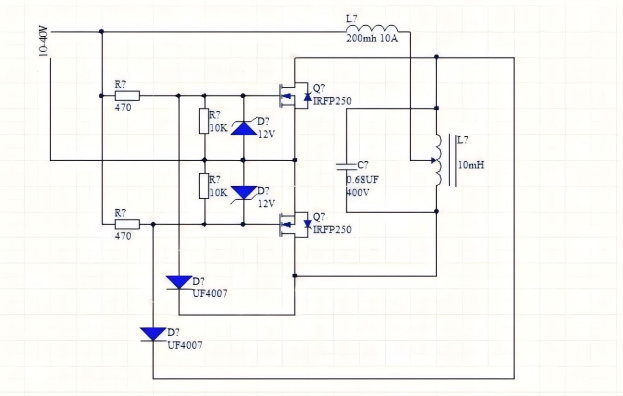
You can follow along to make a simple ABS heater. Based on the basic schematic found online, you'll need to modify it to a non-tapped version. You can select resistors according to the component parameters shown in the schematic, power voltage, and use a 0.24µF capacitor typically used in induction cookers. The MOSFET is an RU7088R from a motorcycle controller, and the diode used is a HER608 fast recovery diode. After assembling everything and powering it on, the system works, but the MOSFET gets very hot during heating.
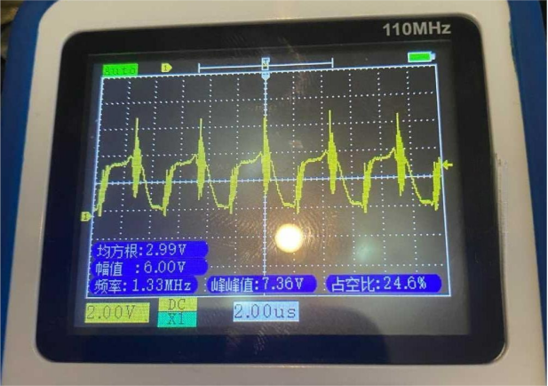
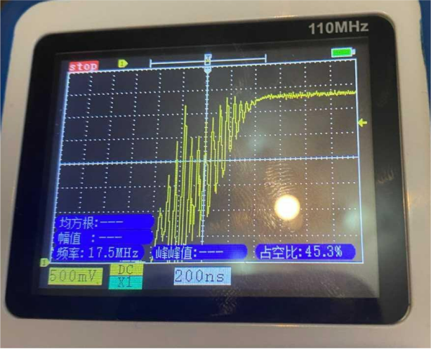
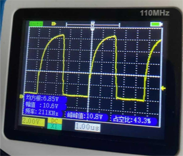
If, while measuring the waveform, you notice high-frequency noise in the gate voltage and noise in the output coil's waveform, try adjusting the 470-ohm resistor value, increasing the voltage, or adjusting the number of turns in the output coil. If the issue persists, the high-frequency noise in the gate may be feedback from the output coil. The original schematic uses the UF4007 diode, but you can replace it with the HER508, which has a reverse recovery time of 25ns. If feedback happens too quickly, you'll need to switch to the RL207, which has a reverse recovery time in the millisecond range, preventing high-frequency noise from affecting the circuit. After replacing it, recheck the waveform—it should now be perfect. The MOSFET stays cool, and the heater's metal strip heats up without any temperature issues in the MOSFET!
At this point, the issue is resolved, and the diode doesn't overheat either. If you experience overheating during your build, try this solution!
The schematic is shown below.


Completed.


