
If you're interested in DIY oscilloscopes, this article is definitely worth a read.
You can easily find some great open-source oscilloscope designs online and use the ideas here as a reference for creating your own PCB. Since powering it through a micro USB isn’t the most convenient option, you'll probably need to redesign the PCB. You can also add a lithium battery with a boost converter and a charging circuit, along with a front panel to make it all look cleaner and more practical that way. The mini oscilloscope shown here uses the STC8A8K64D4 chip. It originally featured a 0.96" OLED display, but you can swap it out for a 1.3" OLED if you prefer.
Here's the PCB layout:
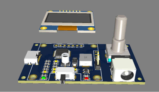
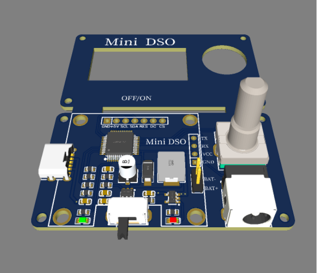
And here's what the assembled board looks like:
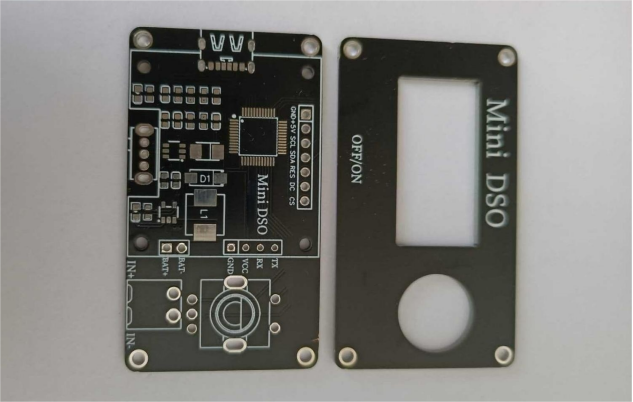
Note: In this version, the board is powered using a 5V charger.
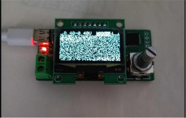
If that setup feels inconvenient, you can modify the soldering stage by adding a lithium battery, boost power supply, charging circuit, and a custom front panel.
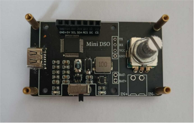
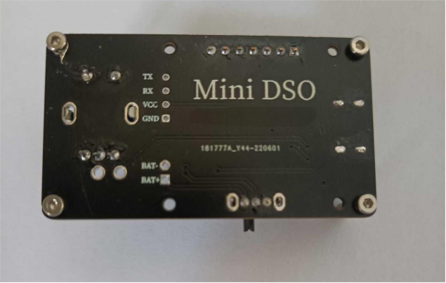
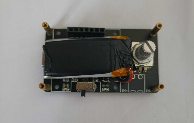
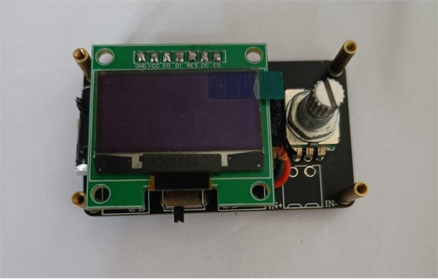
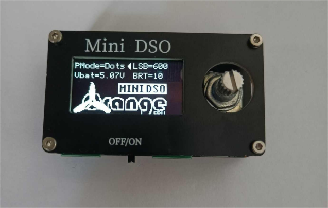
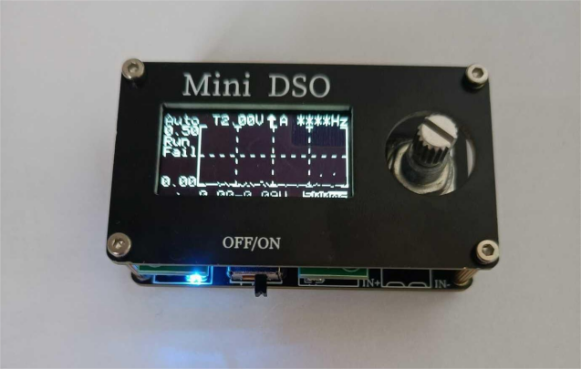
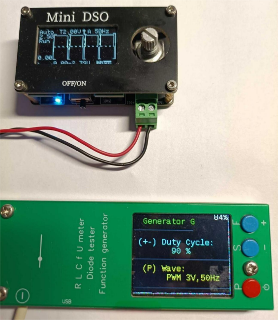
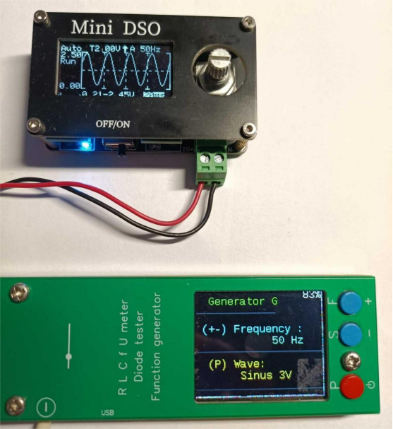
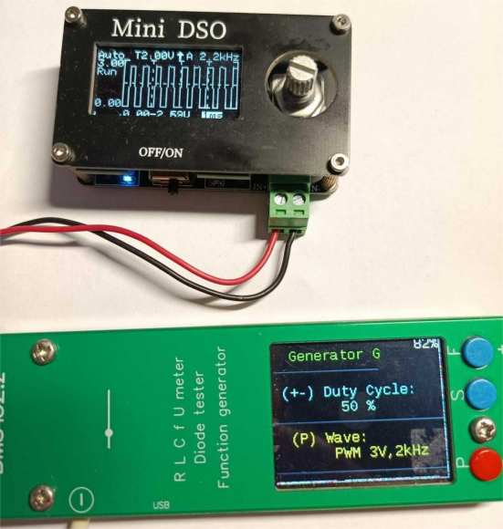
Here's the testing process and the output data:
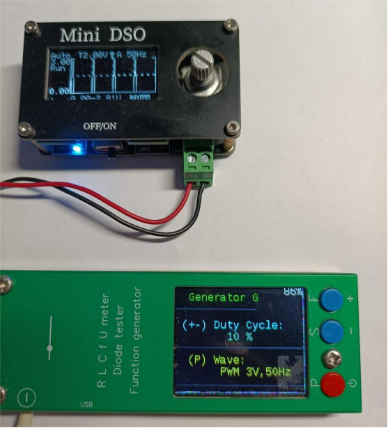
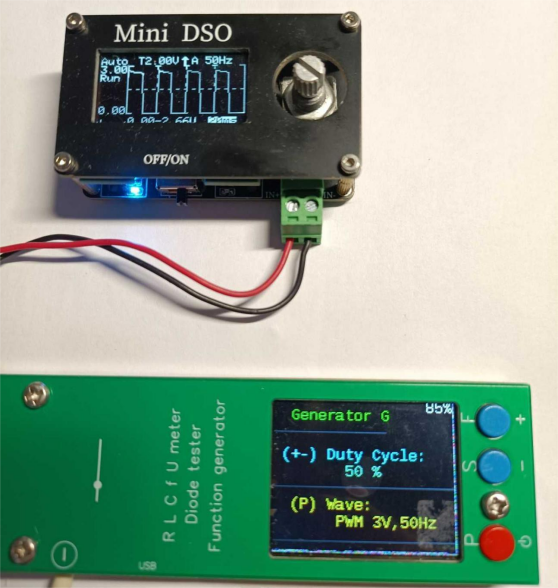
That's a wrap.


