
If you're interested in building your own USB step-down charging board, this guide provides a hands-on look into a high-performance DIY power solution.
In the previous post, DIY: Yonii TC1 Charger Upgrade Guide, we explored the teardown and modification of the Yonii TC1 lithium battery charger. This time, we’ll show you how to build your own power supply hub — ideal for places that suffer from frequent power outages. With PD (Power Delivery) protocol becoming increasingly popular, charging boards can now be upgraded. The main bus voltage can go up to 24V.
The complete power center is planned with five different sub-board designs:
1. LM5176 (PD100W)
2. LM3150 (5V 8A 40W) ×2
3. IP6505T (24W) ×3
4. SW3526 (PD65W) + LM25116 (20V 3.25A 65W)
5. PL5501 ×2 (PD65W)
This project focuses on Sub-Board No. 2, based on the LM3150.
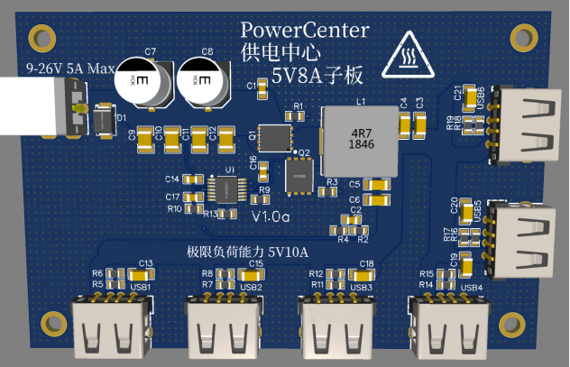
Key Specifications:
· Input Voltage: 9–28V
· Input Current: Max 5A @12V, Max 2.5A @24V
· Output Voltage: 5.2V (pre-compensated due to no load line compensation support)
· Output Current: 8A continuous, 10A peak
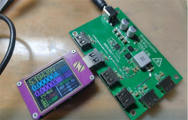
· Protocol Support: DCP/Apple 2.4A
· Efficiency: Up to 93% (13.8V in, 5.2V 8A out)
· Architecture: Buck converter with Constant On-Time (COT) control
Here's a look at the bare PCB:
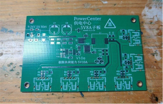
The board measures 100mm × 65mm. Input is on the left side, while output is on the right and bottom (i.e., the lower edge of the PCB).
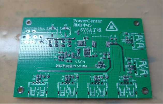
Now it's time to mount the components. Don't forget the 5.1kΩ resistor — without it, the DPDM lines might default to pull-up mode, and you'll lose Apple 2.4A protocol support. But no worries, you can add it later if needed.
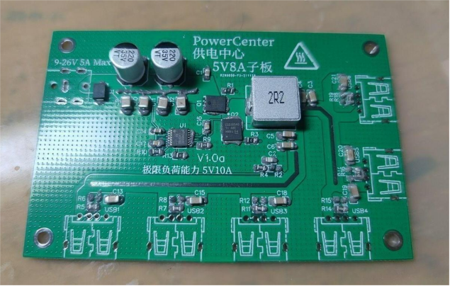
Start by soldering the surface-mount components on one side. A hot plate works great here — set it to 265°C.
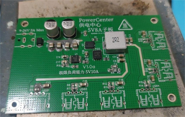
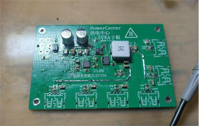
Then, carefully align the components. Let the board cool a bit, and touch up any solder bridges with a soldering iron.
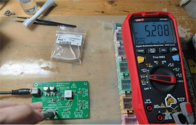
Solder on a DC-007B jack for the 24V power input, and test if the output works correctly.
Next, solder the USB ports.
You can even build another identical board using the same steps and stack them together using copper spacers.
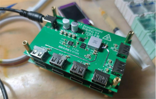
And that's a wrap!


