
If you're interested in DIY-ing a four-wire battery test fixture, this article is worth checking out.
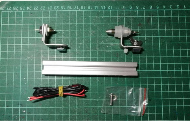
Let's say you have some batteries on hand and want to build a power bank. Before assembling, you'll need to test the batteries—specifically their internal resistance and capacity. If you happen to have an M8V6 on hand, you can even make an external internal resistance tester. But for that, you’ll need a battery test fixture. You can buy one online, of course, but building your own is also an option—just keep in mind the DIY route might cost a bit more. Be sure to use an all-metal setup. A full kit might look like the example below.
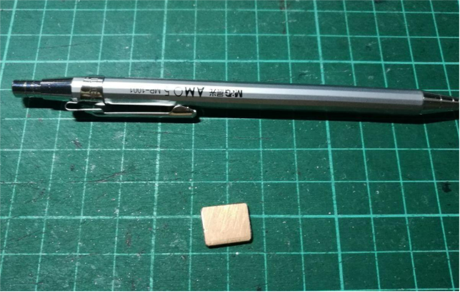
Start by cutting a small piece of double-sided PCB and split it down the middle.
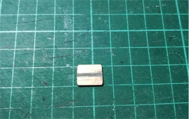
Next, you'll need to solder the wires—make sure both the positive and negative terminals are properly soldered.
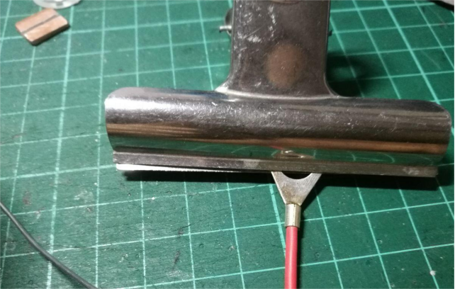
If you're having trouble tinning the negative terminal, try applying a bit of flux to make soldering easier.
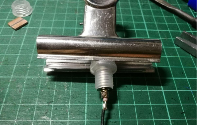
Use dual heat shrink tubing for insulation—the inner one should go on first.
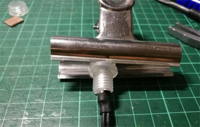
Match the positive and negative terminals before deciding how long the negative wire should be.
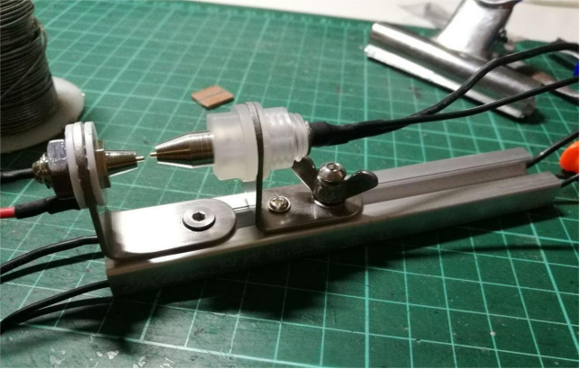
Then solder the wire ends onto the prepped double-sided PCB. This setup allows you to use Kelvin clips for more accurate measurements. Use heat shrink tubing in the middle to tidy up and secure the wires—it helps everything look cleaner and more organized.
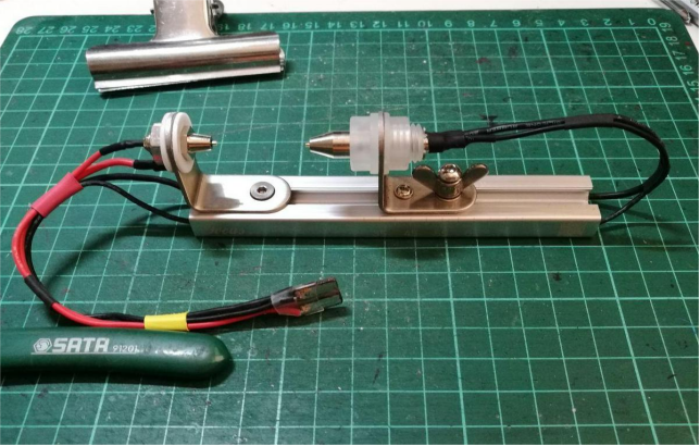
And that's it—you're done.


