
Today is May 20th. In China, “520” (May 20th) is a special day similar to Valentine's Day because the numbers 5-2-0 sound like “I love you” in Chinese. People celebrate by expressing love online, giving gifts, or even getting married!
To celebrate this romantic occasion, we're sharing a hardcore DIY Mechanical Heart gift project from Jiri Praus's creation.
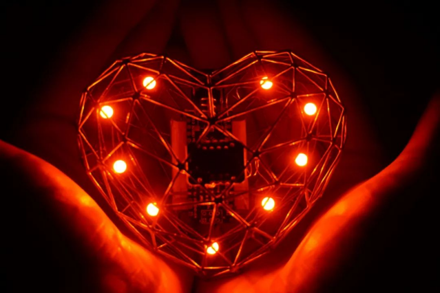
Take advantage of this special day to craft a unique mechanical heart. The outer shell is made from brass wire mesh, and all electronic components are safely enclosed inside, powered by a lithium battery.
Materials & Tools
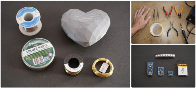
Materials
· 1mm brass wire (5 meters)
· 0.8mm brass wire (5 meters)
· Soldering paste
· 3D-printed heart model11
· STL and GCode files (available at the end)
Electronic Components
· Lithium battery charger module (TP4056)
· Lithium battery
· MAX30102 pulse sensor
· Micro USB breakout board
· 9x WS2812B RGB LEDs
· Mini toggle switch (MSK-12C02)
Tools
· 3mm soldering iron tip
· Pliers
· Wire cutters
· Tweezers
· Double-sided tape
3D Printing the Heart
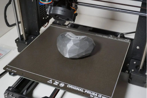
Start by printing the heart using the provided STL files.
The final size is approximately 100 x 84 x 49.5mm, slightly larger than the original model.
You don't need very high precision—it's just a rough structure to guide the brass wire frame.
Preheat your soldering station to 270°C, and get your brass wire and soldering paste ready.
Using the printed heart model as a base, begin shaping the brass wire around one side of the model.
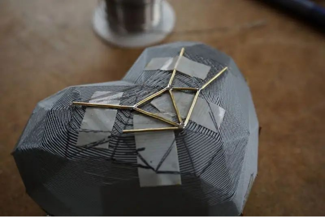
Use double-sided tape to help hold the wire in place as you go.
Start with one wire, then add a second and solder them together.
Add a third to create a stable triangular structure.
Use soldering paste to create smooth, clean joints.
Keep adding and soldering wires until one side is complete.
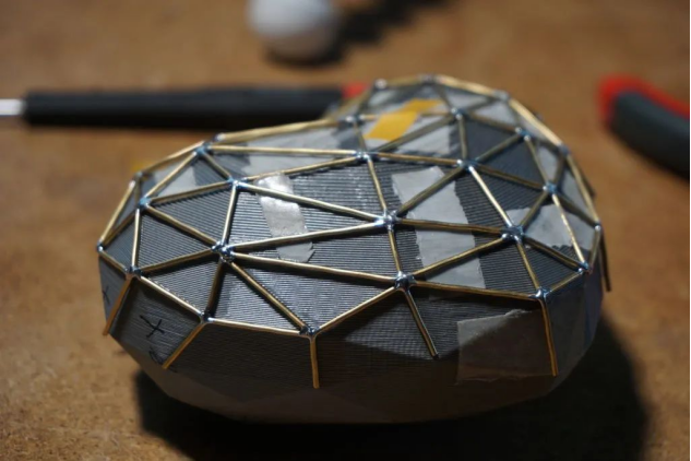
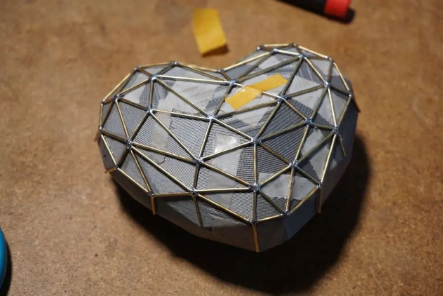
Flip the model and repeat the process for the other side.
Make sure to remove the 3D model before joining both sides of the brass shell together.
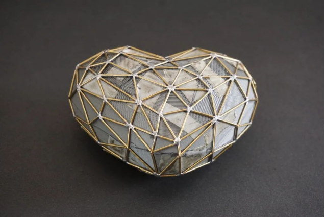
Important: Remove the plastic model before soldering the two halves together!
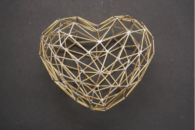
If all goes well, the result should look something like this:
Circuit overview:
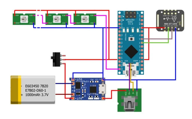
Now that the outer shell is done, it's time to give the heart a “brain.”
The Arduino Nano acts as the core controller. It reads pulse data from the MAX30102 sensor via the I2C bus.
A ring of 9 addressable WS2812B RGB LEDs delivers the visual heart-pulse effect.
Power is provided by the TP4056 battery charging module, which supplies 5V from a lithium battery and can also charge via USB.
Even though both the TP4056 and Arduino Nano have USB ports, you'll still need a separate USB breakout board to split the power and data lines. Without it, the circuit won't function properly.
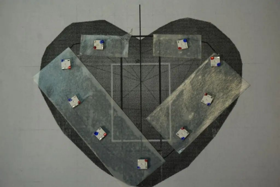
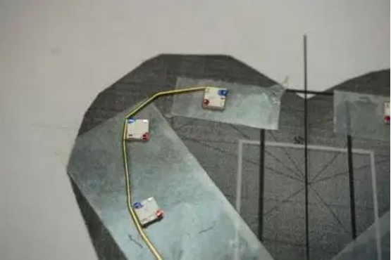
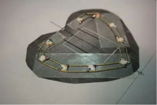
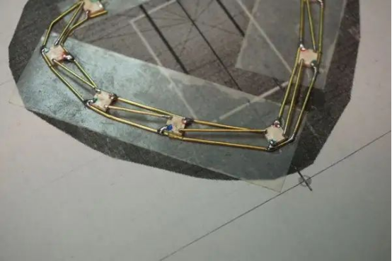
The RGB LED core:
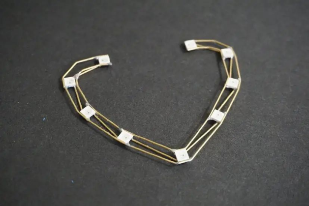
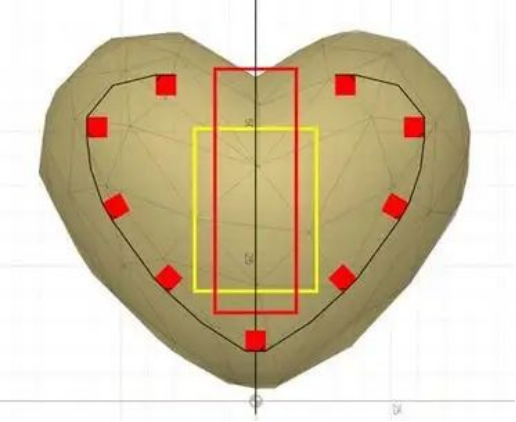
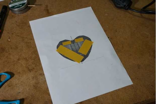
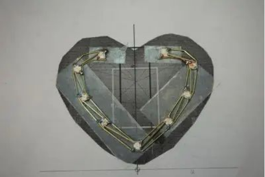
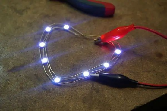
Let's light it up!
To make the inner RGB LED heart:
What You'll Need:
· Cardboard template
· 9x WS2812B RGB LEDs
· 0.8mm brass wire
Steps:
1. Print a heart-shaped LED placement template.
2. Use double-sided tape to secure LEDs upside-down on the red marks.
3. Face the GND pins outward.
4. Bend and solder the outer heart ring to the GND pins.
5. Bend and solder the inner ring to the VCC pins.
6. Chain the LEDs together by connecting the Data Out of one LED to the Data In of the next.
7. Clean the setup with some alcohol.
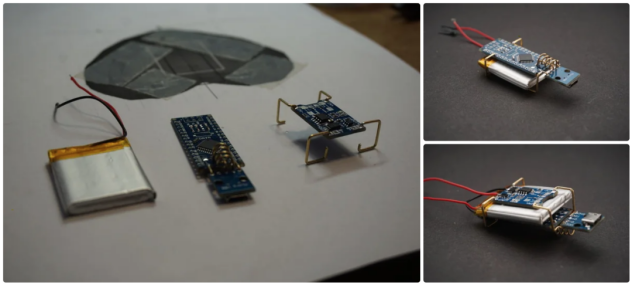
This is the trickiest part and requires basic electronics knowledge.
Powering the Nano with a Lithium Battery:
We'll bypass the Arduino Nano's USB port and power it through a TP4056 module.
This allows you to safely charge the battery and control the heart with an on/off switch.
1. Remove the USB connector from the Arduino Nano.
2. Align and solder the Micro USB breakout board for aesthetics and functionality.
3. Solder TP4056 OUT+ to Arduino 5V and OUT- to GND.
4. Leave space between the Nano and TP4056 for the battery.
5. Connect TP4056 IN+ to the USB board’s power line and IN- to GND.
6. Wire the battery's B+ and B- through a toggle switch to the TP4056 battery pads.
7. Done! Try powering it on.
Pro Tips:
· Remove the Nano's onboard power LED to reduce unwanted light.
· Option 1: Use the onboard USB if you de-solder the bottom rectifier diode.
· Option 2: Use two USB ports—one for programming, one for charging.
· Option 3: If you don't need battery power, skip the USB breakout and charging circuit.
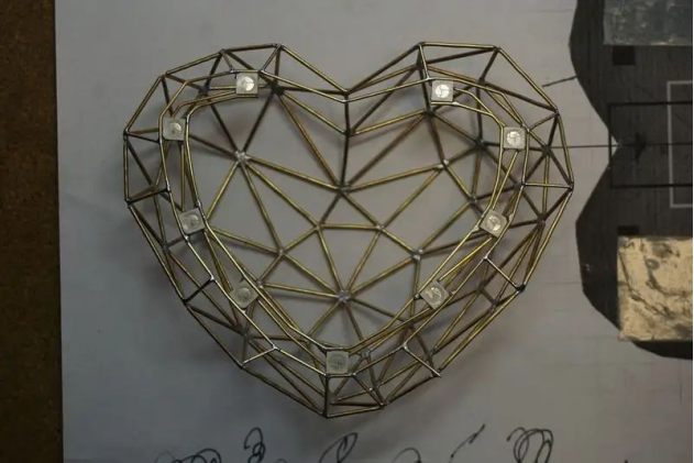
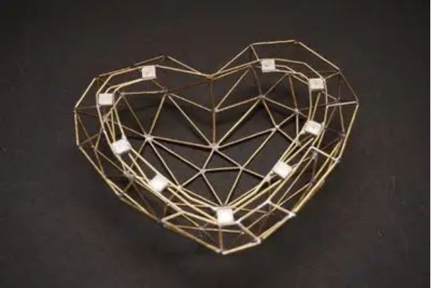
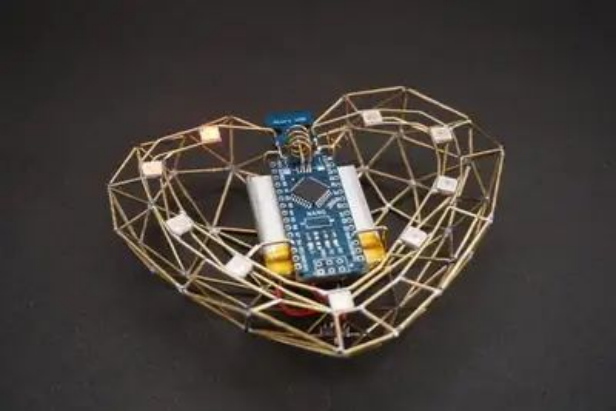
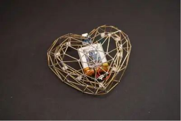
Solder the internal LED heart to the lower half of the brass shell. The outer LED wires are GND, and the shell itself also acts as GND.
Use short brass wires to place the core exactly at the center, like the image shows.
Now, solder the battery and Arduino Nano into place. Use plenty of brass wire to secure everything inside.
Solder the USB breakout's GND to the shell. Do not solder it to the inner copper wires – those carry 5V for the LEDs.
Connect the inner LED wires to the Nano's 5V pin, and connect the first LED's data-in to pin D12.
Installing the Heartbeat Sensor
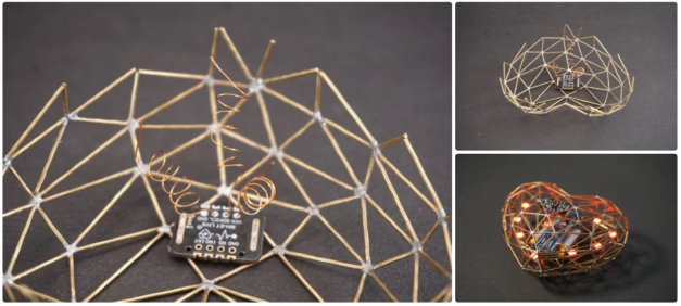
The MAX30102 sensor detects pulse and blood pressure by touch.
Mount the sensor on the upper half of the heart shell. Cut small openings on both sides of the board for grounding – the shell itself is GND.
Make sure the small black sensor component can be touched easily.
Use flexible wires (like 3mm insulated copper) to connect the sensor:
· SCL to A5
· SDA to A6
· VIN to 5V
Test everything before sealing the shell shut!
Upload the Code & Test
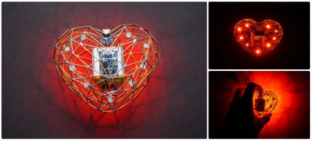
Connect the Arduino to your computer and upload the sketch. Turn on the switch—the red LED on the heartbeat sensor should light up.
When touched, the LED will begin pulsing in sync with your heartbeat. It might take 15 seconds to start reading accurately, so be patient!
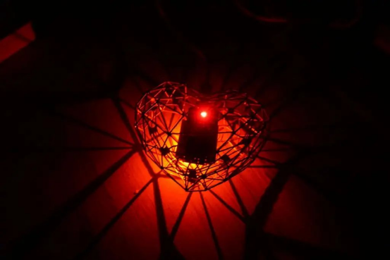
If everything works, solder the top and bottom halves of the heart shell together.
Use alcohol to clean off any leftover flux, and you're done!


