
If you're interested in converting a general-purpose DIY power supply into an adjustable power supply, this article is worth a read.
This tutorial is applicable to both the ADP-220ABB and D220P-01 power supplies. The entire modification process involves adding just 5 components, removing 8 resistors, replacing 1 component, and swapping out 2 output capacitors. If there's any noise after the modification, simply add or replace a surface-mount capacitor.
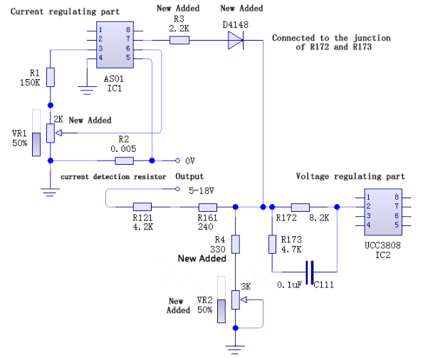
First, let's look at the circuit diagram for the modification:
The modification consists of five main steps:
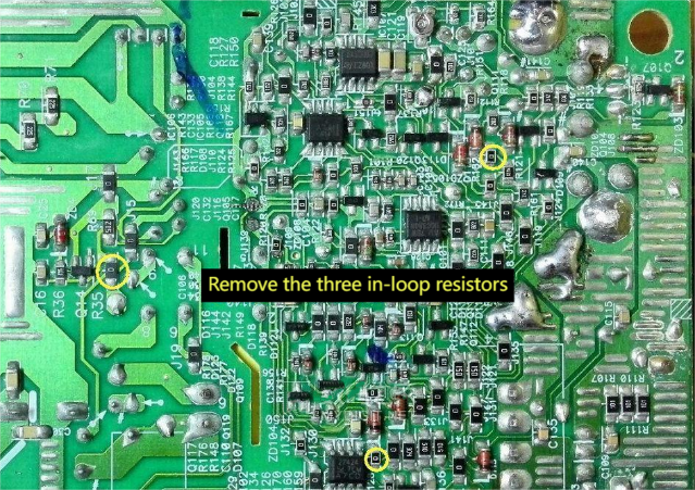
Step 1: Modify the chip's power supply method
In the original setup, the power supply starts up with the auxiliary power, then switches to the main power and shuts off the auxiliary supply. You can change this so that the chip is always powered by the auxiliary supply. To do this, remove the three jumpers as shown below:
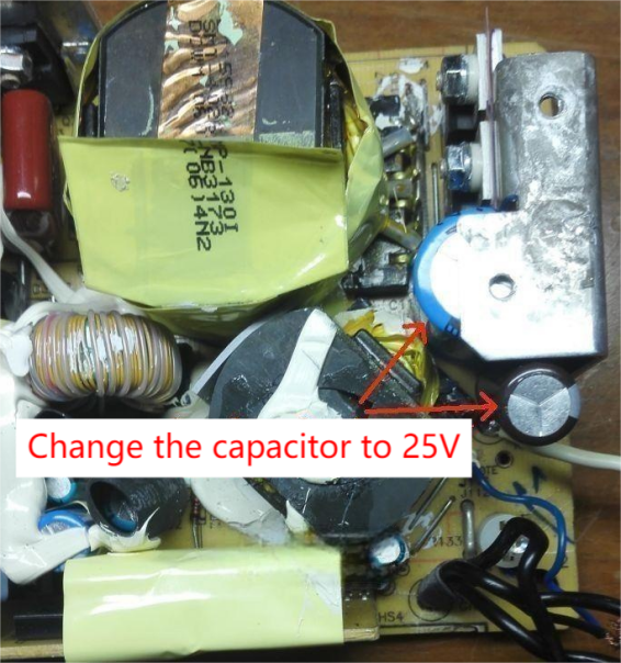
Step 2: Replace the output capacitors with ones rated for 25V
Step 3: Make the voltage adjustable
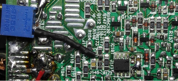
To do this, remove the resistors shown in the image, then add a 330-ohm resistor and a 3K adjustable resistor. Refer to the schematic and the image below for how to connect them.
At this point, the output voltage is adjustable—but don't rush to increase it. Raising the voltage may trigger over-voltage protection and shut the unit down. If you haven't removed the over-voltage protection yet, it's okay to leave it for now. You can remove it later after setting up current adjustment.
Schematic diagram of the voltage adjustment modification:
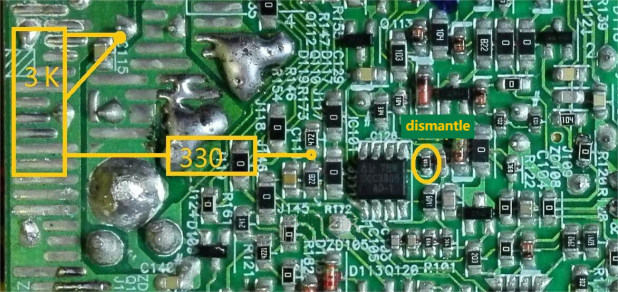
Real photo after voltage adjustment:
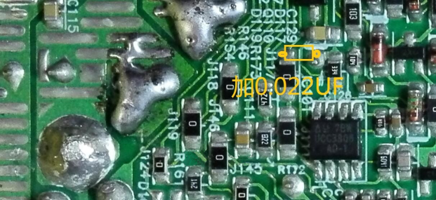
Next, do a quick test on the power supply to check for noise under load. Gradually increase the load current up to 6.5A. If there's noticeable noise, add a 0.022μF surface-mount capacitor in the location shown below. If there's no noise or it's very faint, you can skip this step.
Step 4: Modify the current adjustment
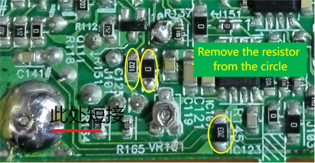
First, remove the three resistors shown in the image. Then, short one wire connection and add a 2.2K resistor, a 4148 diode, and a 2K adjustable resistor. Refer to the schematic and the real photo below for connection points.
Now it's time to remove the original over-voltage protection circuit—otherwise, the power supply won't start. This involves removing a jumper wire.
Schematic diagram of the current adjustment modification:
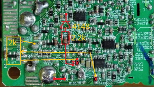
Real photo after current adjustment:
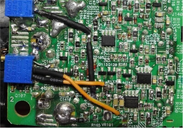
Diagram showing removal of the original protection circuit:
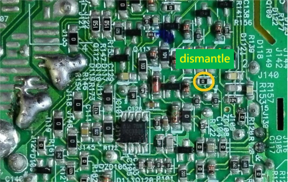
After completing the above steps, the power supply can now support both voltage and current adjustment. However, it's important to test a few things:
1. Test constant current (CC) functionality: Power on the supply with no load. Turn the current adjustment potentiometer to the minimum and observe if the output voltage drops—this is normal. Then, slightly increase the current setting; the voltage should recover, indicating the CC function is working properly.
2. Test current adjustment range: Rotate the current potentiometer from minimum to maximum. The voltage at pin 2 of the AS01 IC should range from 0–0.036V, corresponding to an output current of 0–18A. Actual output may be slightly higher.
3. Test for noise during constant current operation: Slightly increase the current setting, then adjust the output voltage to 15V and connect a 10-ohm load. Slowly reduce the current setting until the voltage begins to drop, and listen for any significant noise. If you hear noise, power off immediately and replace the capacitor in the position shown below with one rated between 0.1–1μF. This should eliminate or reduce the noise.
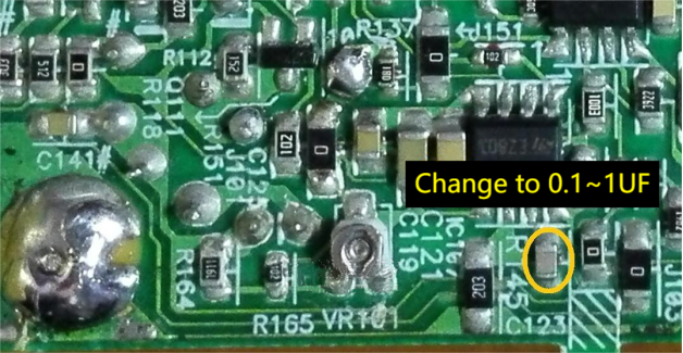
Step 5: Modify the power-on indicator (optional)
Originally, the power-on indicator light doesn't turn on if the output voltage is below 10V. After this modification, it will.
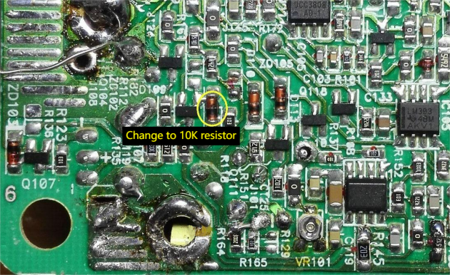
Once you've completed all five steps, you'll have a powerful, stable, and fully adjustable power supply ready to serve your DIY needs.


